


Appendix 2. Selection
A2 - 2
Appendix 2-1 Selection of servomotor capacity
The following three elements are used to determine the servomotor capacity.
1. Load inertia ratio
2. Short time characteristics (acceleration/deceleration torque)
3. Continuous characteristics (continuous effective load torque)
Carry out appropriate measures, such as changing the motor series or increasing the motor capacity, if
any of the above conditions is not fulfilled.
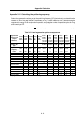
Appendix 2-1-1 Load inertia ratio
Each servomotor has an appropriate load inertia ratio (load inertia/motor inertia). The control becomes
unstable when the load inertia ratio is too large, and the servo parameter adjustment becomes difficult.
It becomes difficult to improve the surface precision in the feed axis, and the positioning time cannot be
shortened in the positioning axis because the settling time is longer.
If the load inertia ratio exceeds the recommended value in the servomotor specifications list, increase
the motor capacity and limit the load inertia ratio within the recommended value. Note that the
recommended value for the load inertia ratio is strictly one guideline. This does not mean that controlling
of the load with inertia exceeding the recommended value is impossible.
POINT
1. When selecting feed axis servomotors for NC unit machine tools, place
importance on the surface precision during machining. To do this, always
select a servomotor with a load inertia ratio within the recommended value.
Select the lowest value possible within that range.
2. Judge the load inertia ratio for the motor with brakes using the motor inertia of
motors without brakes as a reference.
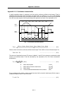
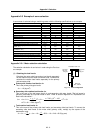
Appendix 2-1-2 Short time characteristics
In addition to the continuous operation range, the servomotor has the short time operation range that
can only be used for short times such as acceleration/deceleration. This range is expressed at the
maximum torque. The maximum torque differs for each motor even at the same capacity, so confirm the
specifications in section "2-1 Servomotor".
The maximum torque affects the acceleration/deceleration time constant that can be driven. The linear
acceleration/deceleration time constant ta can be approximated from the machine specifications using
expression (2-1). Determine the maximum motor torque required from this expression, and select the
motor capacity.
ta =
(J
L
+ J
M
) N
95.5 (0.8 T
MAX
T
L
)
(ms) .................................................. (2-1)
N : Motor reach speed (r/min)
J
L : Motor shaft conversion load inertia (kg
.
cm
2
)
J
M : Motor inertia (kg
.
cm
2
)
T
MAX : Maximum motor torque (N
.
m)
T
L : Motor shaft conversion load (friction, unbalance) torque (N
.
m)