


9. Adjustment
9 - 2
9-1 Servo adjustment data output function (D/A output)
The MDS-R-V1/V2 servo drive unit has a function to D/A output the various control data.
The servo adjustment data required for setting the servo parameters to match the machine can be D/A
output. Measure using a high-speed waveform recorder, synchroscope, etc.
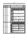
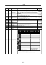
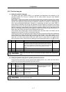
9-1-1 D/A output specifications
Item Explanation
No. of channels 2ch
Output cycle 0.8ms (Min. value)
Output precision 12bit
Output voltage range 0~2.5~5V
Output magnification
setting
±1/256 to ±128-fold
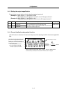
Output pins
CN9 connector
Channel 1 = Pin 4
Channel 2 = Pin 14
GND (LG) = Pins 1
Function
Phase current feedback output function
L axis U phase current FB : pin 6
L axis V phase current FB : pin 16
M axis U phase current FB : pin 7
M axis V phase current FB : pin 17
Option
Relay terminal block: MR-J2CN3TM
Lead out with the SH21 cable from
the CN9 connector and connect.
CN9 connector
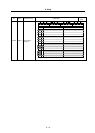
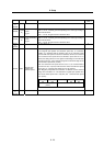
9-1-2 Setting the output data
No. Abbrev. Parameter name Explanation
SV061 DA1NO
D/A output channel 1
data No.
SV062 DA2NO
D/A output channel 2
data No.
Input the No. of the data to be output to each D/A output channel.
(Note) When using the 2-axis drive unit (MDS-R-V2), set "0" for the data No. of the
other axis in the same drive unit which is not to be D/A output.
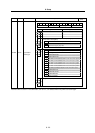
No. Output data
Standard
output unit
Output
cycle
No. Output data
Standard
output unit
Output
cycle
0 D/A output not selected
1 Speed feedback 1000 r/min / 0.5V 0.8ms 21 Load level 100%/0.5V 0.1s
2 Current feedback Stall current/0.5V 0.8ms 22
3 Speed command 1000 r/min / 0.5V 0.8ms 23 Regeneration load level 100%/0.5V 0.9s
4 Current command Stall current/0.5V 0.8ms 24
5 25
6 26
7
Estimated
disturbance torque
Stall current/0.5V 0.8ms 27
8 28
9 29
10
30
11 Position droop mm/0.5V 3.5ms
12 Position droop (×10)
100m/0.5V
3.5ms
13 Position droop (×100)
10m/0.5V
3.5ms
31 ~ 99
No setting
14 Feedrate (F∆T) 10000(mm/min)/0.5V 0.8ms 100 2.5V test output – –
15 Feedrate (F∆T×10) 1000(mm/min)/0.5V 0.8ms
16 Model position droop mm/0.5V 3.5ms
101
Sawtooth wave test
output
0 to 5V
Cycle 113.7ms
0.8ms
17
Model position droop
(×10)
100m/0.5V
3.5ms 102
Short wave test output 0 to 5V
Cycle 227.5ms
0.8ms
18
Model position droop
(×100)
10m/0.5V
3.5ms
19
20
103 ~
Setting prohibited
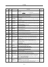
9
Si
g
nal
MO1
LG
COM
SG
MUIFB
LUIFB
2
VDD
5
1
Pin
6
4
3
10
7
8
19
Si
g
nal
MO2
MC
MBR
MVIFB
LVIFB
12
EMGX
15
11
Pin
16
14
13
20
17
18