


10. Troubleshooting
10 - 5
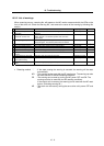
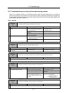
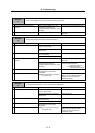
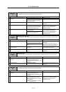
No. Alarm name Alarm details Stopping method Reset
43 Feedback error 2 An excessive difference in feedback was detected between the
sub side detector and the main side detector.
Dynamic brakes
PR
45 Fan stop A cooling fan built in the drive unit stopped, and the loads on the
unit exceeded the specified value.
Deceleration control
NR
46 Motor overheat Thermal protection function of the motor or in the detector, has
started its operation.
Deceleration control
NR
50 Overload 1 Overload detection level became over 100%. The motor or the
drive unit is overloaded.
Deceleration control
NR
51 Overload 2 Current command of more than 95% of the unit's max. current
was being continuously given for longer than 1 second.
Dynamic brakes
NR
52 Excessive error 1 A difference between the actual and theoretical motor positions
during servo ON exceeded the setting value.
Dynamic brakes
NR
53 Excessive error 2 A difference between the actual and theoretical motor positions
during servo OFF exceeded the setting value.
Dynamic brakes
NR
54 Excessive error 3 The anomalous motor current was detected at the detection of
Excessive error 1.
Dynamic brakes
NR
55 External emergency stop error There is no contactor shutoff command, even after 30 seconds
has passed since the external emergency stop was input.
Dynamic brakes
NR
5F External contactor error A contact of the external contactor is welding. Or the contactor
fails to be ON during ready ON.
Deceleration control
NR
88 Watchdog The system does not operate correctly. Dynamic brakes
AR
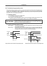
(Note) Definitions of terms in the table are as follows.
Main side detector: Detector connected to CN2 Sub side detector: Detector connected to CN3
Stopping method Deceleration control : The motor stops with the deceleration control time
constants set with the parameters (SV056).
Dynamic brakes : The dynamic brakes activate simultaneously with the
alarm occurrence to stop the motor.
Initial error : This alarm is detected before ready ON.
Resetting method NR : The alarm can be reset with the NC reset button. The alarm can also be
reset with the PR and AR resetting conditions.
PR : The alarm can be reset by turning the NC power OFF and ON. The alarm
can also be reset with the AR resetting conditions.
If the control axis is removed, the alarm can be reset with the NC reset
button. (Excluding alarms 32 and 37.)
AR : The alarm can be reset by turning the servo drive unit's power OFF and
ON.