


Appendix 2. Selection
A2 - 4
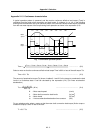
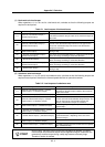
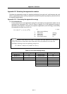
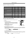
(1) Horizontal axis load torque
When operations <1> to <8> are for a horizontal axis, calculate so that the following torques are
required in each period.
Table 2-1 Load torques of horizontal axes
Period Load torque calculation method Explanation
<1>
(Amount of acceleration torque) +
(Kinetic friction torque)
Normally the acceleration/deceleration time constant is
calculated so that this torque is 80% of the maximum torque of
the motor.
<2> (Kinetic friction torque)
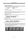
<3>
(Amount of deceleration torque) +
(Kinetic friction torque)
The absolute value of the acceleration torque amount is same
as that of the deceleration torque amount. The signs for the
amount of acceleration torque and amount of deceleration
torque are reversed.
<4> (Static friction torque)
Calculate so that the static friction torque is always required
during a stop.
<5>
(Amount of acceleration torque)
(Kinetic friction torque)
The signs are reversed with period <1> when the kinetic friction
does not change according to movement direction.
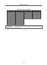
<6>
(Kinetic friction torque)
The signs are reversed with period <2> when the kinetic friction
does not change according to movement direction.
<7>
(Amount of deceleration torque)
(Kinetic friction torque)
The signs are reversed with period <3> when the kinetic friction
does not change according to movement direction.
<8>
(Static friction torque)
Calculate so that the static friction torque is always required
during a stop.
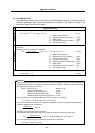
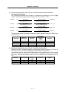
(2) Unbalance axis load torque
When operations <1> to <8> are for an unbalance axis, calculate so that the following torques are
required in each period. Note that the forward speed shall be an upward movement.
Table 2-2 Load torques of unbalance axes
Period Load torque calculation method Explanation
<1>
(Amount of acceleration torque) + (Kinetic
friction torque) + (Unbalance torque)
Normally the acceleration/deceleration time constant is
calculated so that this torque is 80% of the maximum
torque of the motor.
<2> (Kinetic friction torque) + (Unbalance torque)
<3>
(Amount of deceleration torque) + (Kinetic
friction torque) + (Unbalance torque)
The absolute value of the acceleration torque amount
is same as that of the deceleration torque amount. The
signs for the amount of acceleration torque and
amount of deceleration torque are reversed.
<4> (Static friction torque) + (Unbalance torque)
The holding torque during a stop becomes fairly large.
(Upward stop)
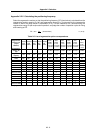
<5>
(Amount of acceleration torque) (Kinetic
friction torque) + (Unbalance torque)
<6>
(Kinetic friction torque) + (Unbalance torque)
The generated torque may be in the reverse of the
movement direction, depending on the size of the
unbalance torque.
<7>
(Amount of deceleration torque) (Kinetic
friction torque) + (Unbalance torque)
<8>
(Static friction torque) + (Unbalance torque)
The holding torque becomes smaller than the upward
stop. (Downward stop)
POINT
During a stop, the static friction torque may constantly be applied. The static
friction torque and unbalance torque may be applied during an unbalance axis
upward stop, and the torque during a stop may become extremely large.
Therefore, caution is advised.