


7. Wiring and Connection
7 - 7
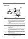
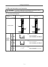
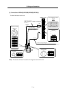
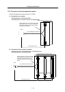
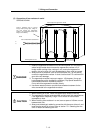
7-4 Motor and detector connection
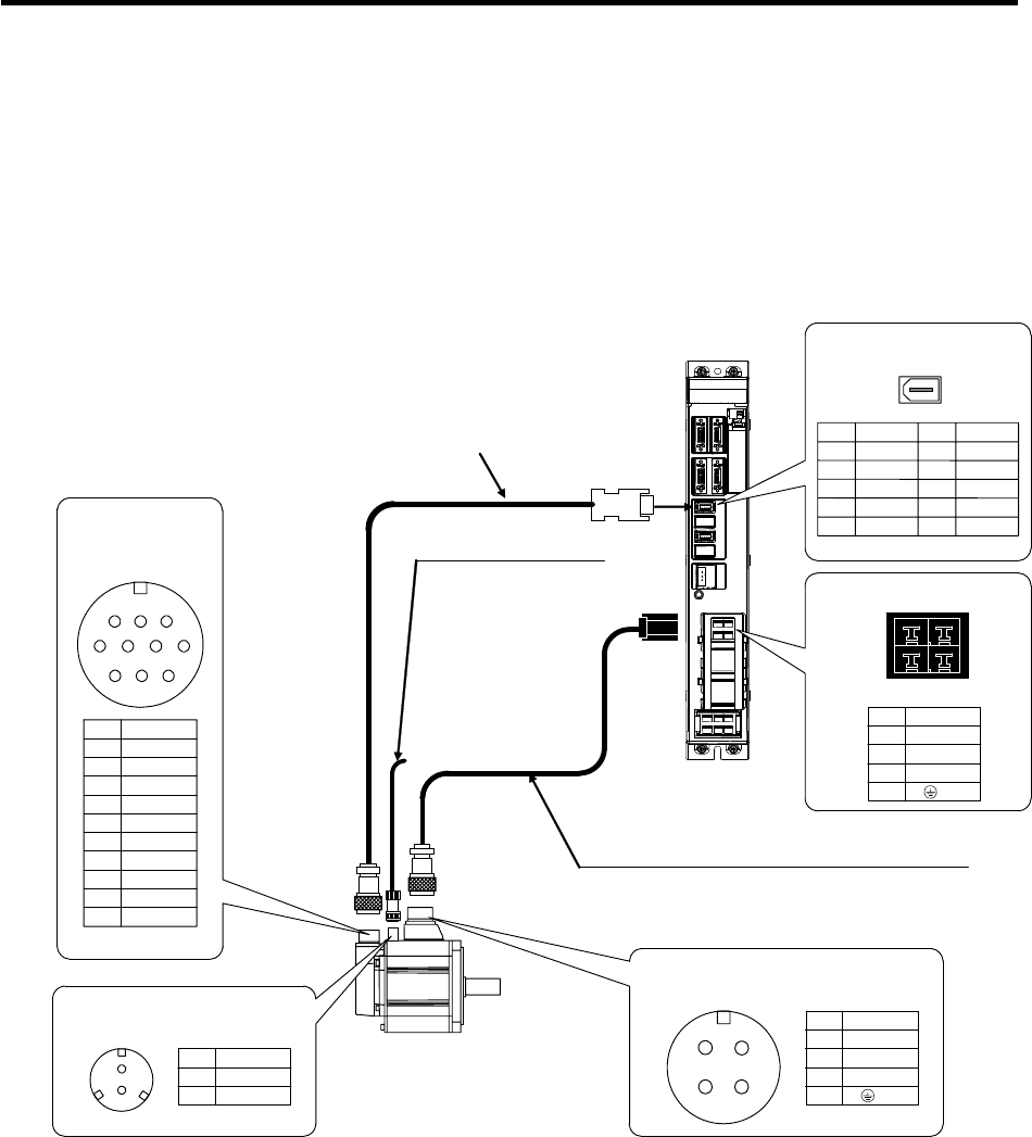
7-4-1 Connection of servomotor HF Series
(1) Connection of HF75(B)/HF105(B)/HF54(B)/HF104(B)/HF154(B)/HF224(B) /HF123(B)
/HF223(B)/HF142(B)
The A48 or A51 detector can be used.
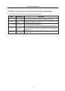
Pin
1
2
3
4
5
6
7
8
9
10
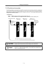
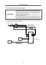
Servomotor
(Refer to “7-8 Wiring of the
motor brake” for details.)
Motor brake wiring
MDS-R-V1/V2
Max. 30m
CN2L
Option cable:CNV2E
(Refer to Appendix 1 for details on manufacturing
the cable.)
CN31L
Power wire and grounding wire
(Refer to “5-1 Selectin
g
the wire size" for details on selectin
g
the wire.)
U,V,W,PE
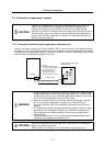
CM10-R10P
Detector connector
Signal
RQ
RQ*
BAT
LG(GND)
SD
SD*
P5(+5V)
SHD
1 2
10
4
3
9
6 5
8
7
There is no
p
olarit
y
for 24VDC.
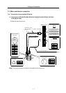
Pin
1
2
Signal
B1
B2
Brake connector
CM10-R2P
A
B C
D
Pin
A
B
C
D
Signal
U
V
W
PE
Power connector
MS3102A18-10P
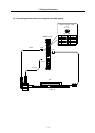
Motor side detector connector
CN2L/M
Signal
P5
LG
RQ
RQ*
Pin
1
2
3
4
5
Signal
SD
SD*
BAT
Pin
6
7
8
9
10
Motor power connector
CN31L/M
1 2
Pin
1B
1A
2B
2A
Signal
V
W
PE
B
A
1
2
(Note) The above connection is used for the single-axis servo drive unit.