


Appendix 2. Selection
A2 - 12
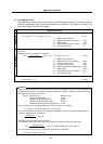
Appendix 2-3-2 Regenerative resistor selection calculation
Calculation is carried out in order with the Z axis as an example.
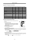
(1) Obtaining the generated torque
The deceleration torque required to calculate the regenerative energy is obtained.
Upward stop deceleration torque: T
du
The amount of deceleration torque (=amount of acceleration torque) is first calculated using
expression (2-4).
(JL+JM)N (32.2+47.9)3000
T
a=
95.5
ta
=
95.5
100
= 25.2 (N
m)
The upward stop deceleration torque is obtained from the amount of deceleration torque,
unbalance torque and friction torque.
Tdu = Ta–TU–TF = 25.2-5.3-0.27 = 19.6 (Nm)
Downward stop deceleration torque: T
dd
The downward stop deceleration torque is obtained from the amount of deceleration torque,
unbalance torque and friction torque.
Tdd = Ta+TU–TF = 25.2+5.3-0.27 = 30.2 (Nm)
Upward torque during dropping: Ts
The upward torque during dropping is obtained from the unbalance torque and friction torque.
Ts = TU–TF = 5.3-0.27 = 5.6 (Nm)
Constant speed travel: L
Because the constant speed travel is not clearly described in the specifications, the value used
here is 200mm taking the axis stroke, etc., into consideration.
(2) Obtaining the regenerative energy
Because the Z axis is a vertical axis, the regenerative energy is calculated separately for an upward
stop and downward stop.
Upward stop regenerative energy: E
RU
This is obtained from expression (2-7).
ERU = 5.2410
-5
Tdu N td – Ec = 5.2410
-5
0.8519.63000100-46 = 215.9 (J)
Downward stop regenerative energy: E
RU
This is obtained from expression (2-8).
2 Ts L
E
RD =
∆S
+ 5.2410
-5
Tdd N td – Ec
2
0.855.62003
=
10
2
+ 5.24
10
-5
0.8530.23000100-46
= 897.2+403.5
-46 = 1254.7 (J)
Stop regenerative energy per cycle: E
R
This is obtained from expression (2-9).
ER = 215.9+1254.7 = 1470.6 (J)