


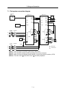
7. Wiring and Connection
7 - 6
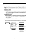
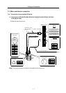
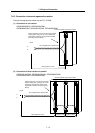
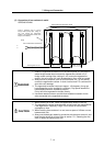
7-3 NC and drive unit connection
The NC bus cables are connected from the NC to each drive unit so that they are laid in a straight line
from the NC to the terminal connector (battery unit). And up to 7 axes can be connected per system.
(Note that the number of connected axes is limited by the CNC. The following drawing shows an
example with 5 axes connected.)
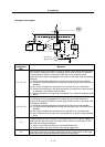
< Connection >
CN1A : CN1B connector on NC or previous stage's drive unit
CN1B : CN1A connector on next stage's drive unit or terminal connector (battery unit)
Max. length of 30m from the NC to the terminal connector.
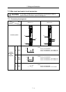
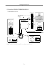
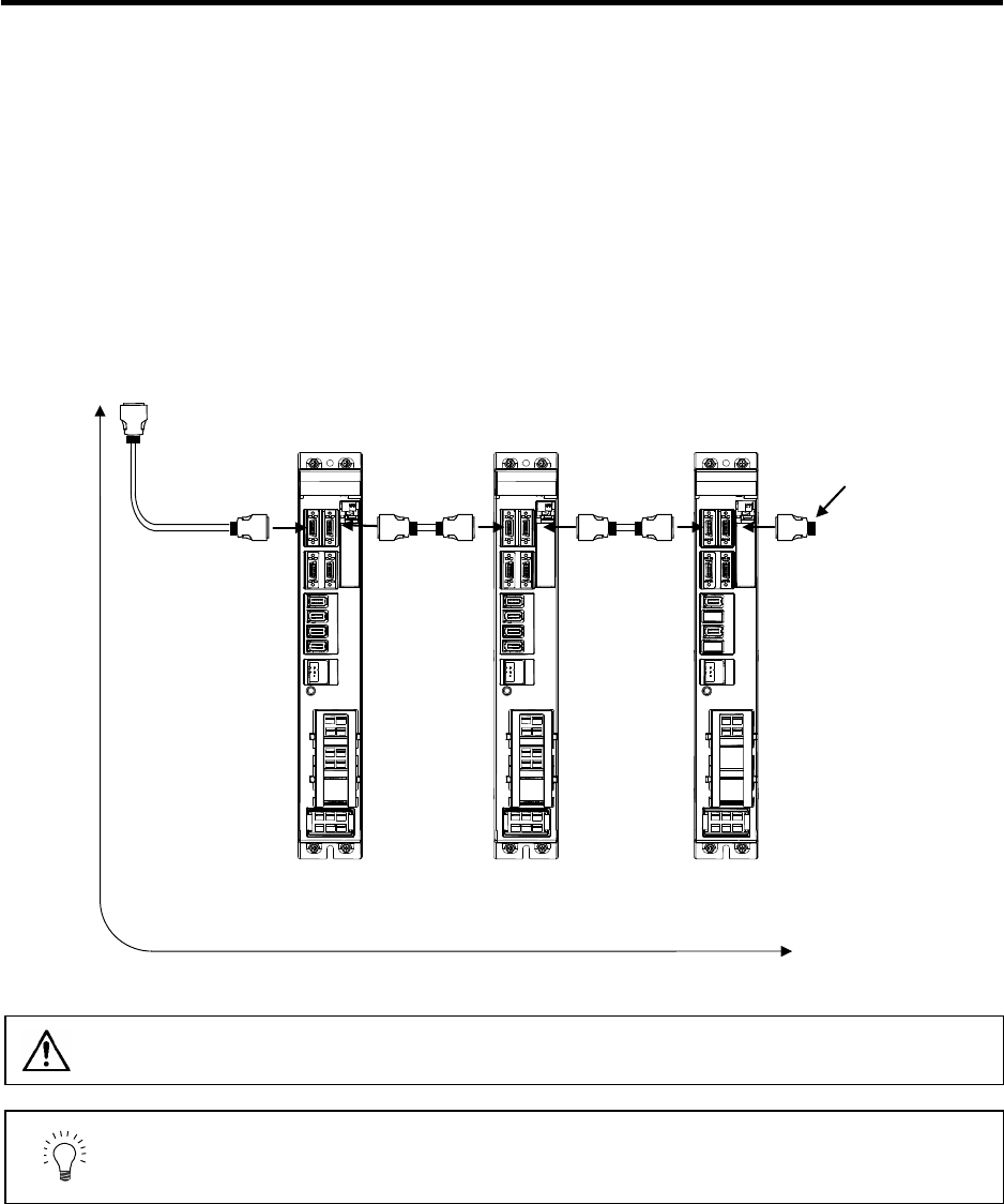
Connect to the
battery unit with a
terminal connector
or SH21 cable.
MDS-R-V1-
5th axis (final axis)
MDS-R-V2-
3rd/4th axis
MDS-R-V2-
1st/2nd axis
Connected to the NC
Refer to the
instruction manual
of each NC for
details.
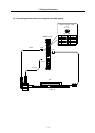
CN1B CN1
A
CN1B
CN1
A
CN1B
CN1
A
SH21 cable
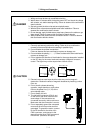
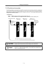
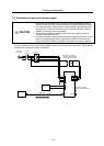
CAUTION
Wire the SH21 cable between the NC and drive unit so that the distance
between the NC and terminal connector (battery unit) is within 30m.
POINT
Axis Nos. are determined by the rotary switch for setting the axis No. (Refer to
section "8-1-1 Setting the rotary switch".) The axis No. has no relation to the
order for connecting to the NC.