


Appendix 2. Selection
A2 - 3
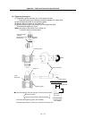
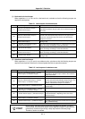
Appendix 2-1-3 Continuous characteristics
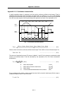
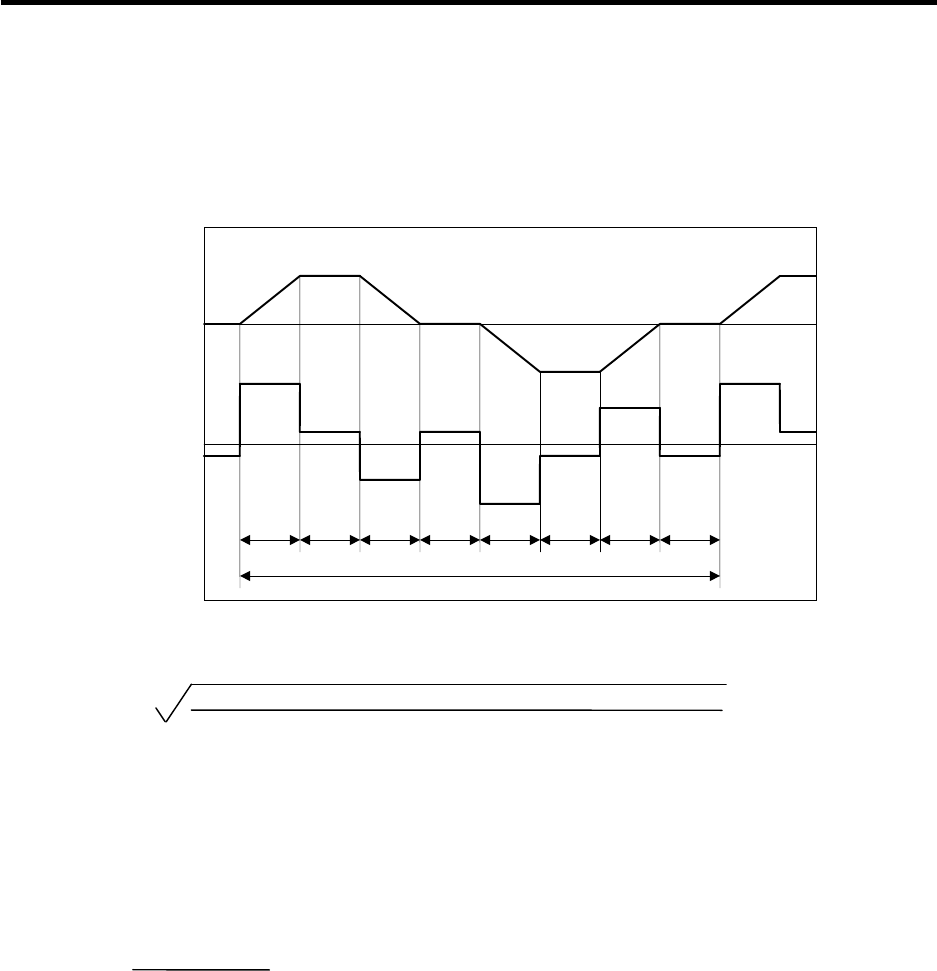
A typical operation pattern is assumed, and the motor's continuous effective load torque (Trms) is
calculated from the motor shaft conversion and load torque. If numbers <1> to <8> in the following
drawing were considered a one-cycle operation pattern, the continuous effective load torque is obtained
from the root mean square of the torque during each operation as shown in the expression (2-2).
Motor
torque
Motor
speed
0
0
T
3
T
2
t
1
t
2
t
3
t
4
t
0
T
1
Time
T
4
T
5
T
6
T
7
T
8
t
5
t
6
t
7
t
8
<1> <2> <3> <4> <5> <6> <7> <8>
Fig. 1 Continuous operation pattern
Trms =
T1
2
·t1 + T2
2
·t2 + T3
2
·t3 + T4
2
·t4 + T5
2
·t5 + T6
2
·t6 + T7
2
·t7 + T8
2
·t8
t0
.................... (2-2)
Select a motor so that the continuous effective load torque Trms is 80% or less of the stall torque Tst.
Trms ≤ 0.8
.
Tst .................................................. (2-3)
The amount of acceleration torque (Ta) shown in tables 2-1 and 2-2 is the torque to accelerate the load
inertia in a frictionless state. It can be calculated by the expression (2-4). (For linear acceleration/
deceleration)
Ta =
(J
L
+ J
M
) N
95.5
ta
(N
.
m) .................................................. (2-4)
N : Motor reach speed (r/min)
J
L : Motor shaft conversion load inertia (kg
.
cm
2
)
J
M : Motor inertia (kg
.
cm
2
)
ta : Linear acceleration/deceleration time constant (ms)
For an unbalance axis, select a motor so that the motor shaft conversion load torque (friction torque +
unbalance torque) is 60% or less of the stall.
T
L
≤ 0.6
.
Tst .................................................. (2-5)