


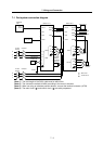
7. Wiring and Connection
7 - 11
7-6 Connection of regenerative resistor
CAUTION
The MDS-R Series does not have a built-in regenerative resistor. If the load
inertia is small, there will be no problem with the capacitor regeneration
(regenerative resistance is not required as the circuit is charged with the
capacitor in the drive unit). However, the overvoltage alarm (ALM33) will occur if
the load inertia is large. In this case, connect the external option regenerative
resistor. Refer to section "Appendix 2-2 Selection of regenerative resistor" for
details on making a selection.
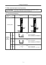
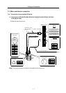
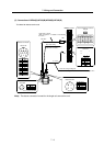
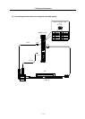
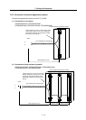
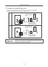
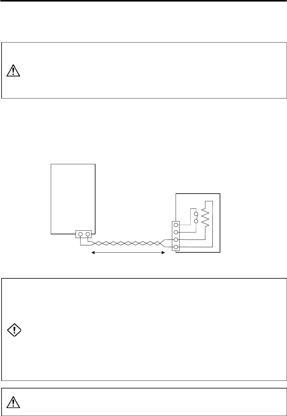
7-6-1 Connection of external option regeneration resistance unit
Connect the option regeneration resistor between the P and C terminals. The thermal protector
terminals (G3, G4) are used together with the electronic thermal to provide double-protection against
overheating of the regenerative resistor. Construct a sequence in which an emergency stop results
when the current stops flowing between G3 and G4.
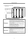
MDS-R-V1/V2
CN30
External option regeneration
resistance unit
P
C
G4
G3
P C
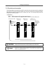
G3 and G4:
Thermal protector terminals
The current stops flowing between
G3 and G4 when there is
abnormal overheating.
Contact capacity: 150mA
Contact ON resistance: 10m
Twist the wires.
5m or less
DANGER
1. Install the regenerative resistor unit in the control panel or in the place where
foreign matter does not enter the regenerative resistor unit. If foreign matter
(cutting chips, cutting oil, etc.) enters the regenerative resistor unit, the servo
drive unit could be damaged or fires could be caused.
2. Select the installation place so that foreign matter (cutting chips, cutting oil,
etc.) do not enter the regenerative resistance unit's terminal block. A
short-circuit between the P and C terminals could lead to servo drive unit
damage.
3. The regenerative resistor generates heat of approximately 100°C (or higher,
depending on the installation conditions). Give sufficient consideration to
heat dissipation and installation position. Do not touch the regenerative
resistor directly.
4. Use flame retardant wire or provide flame retardant treatment for the wire
connected to the regenerative resistance unit.
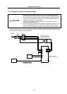
CAUTION
Always use twisted pair cable to connect to the servo drive unit, and keep the
length of the wiring to 5m or less.
Refer to section "5-1 Selection of wire" for details on selecting the wire.