


Appendix 2. Selection
A2 - 9
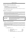
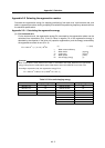
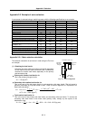
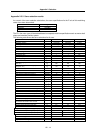
Appendix 2-3 Example of servo selection
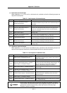
A servomotor is selected using a machining center with the following specifications as an example.
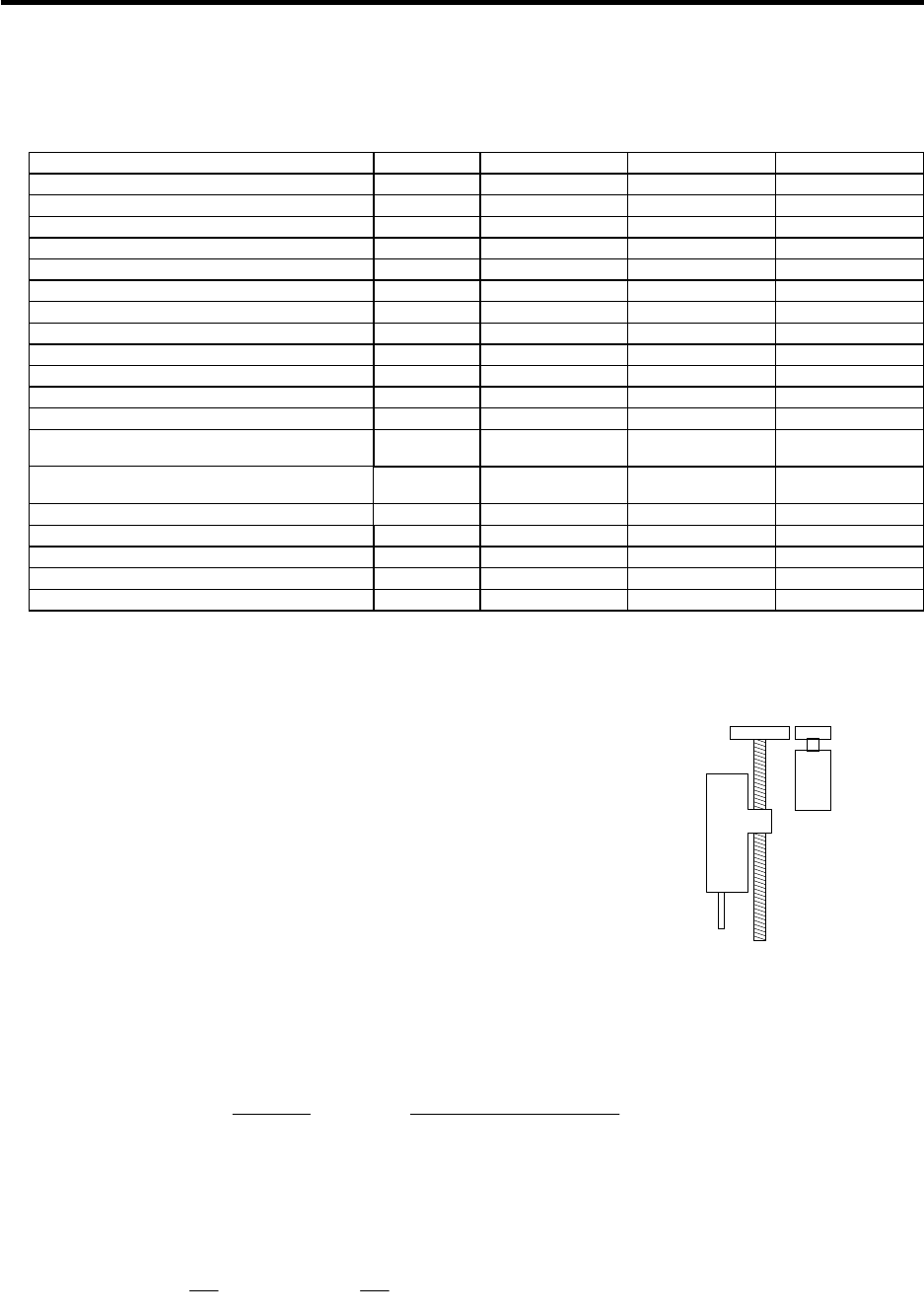
Specification item Unit X axis Y axis Z axis
Axis type Linear Linear Linear
Movement direction Horizontal Horizontal Vertical
Table support method Rolling Rolling Rolling
Table movement friction coefficient % 5 5 5
Ball screw diameter mm 50 50 50
Ball screw length mm 1200 1000 1000
Ball screw lead mm 10 10 10
Deceleration ratio 1 1 2/3
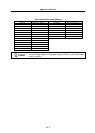
Primary side gear inertia kg
.
cm
2
1.6
Secondary side gear inertia kg
.
cm
2
8.1
Motor/ball screw connection section inertia kg
.
cm
2
10.0 10.0
Mass of moving object installed on the machine
(table, etc.)
kg 600 500 500
Mass of standard-added-moving object
(workpiece, etc.)
kg 100 100 10
Rapid traverse rate mm/min 30000 30000 20000
Target acceleration/deceleration time constant ms 120 120 100
Rapid traverse positioning frequency times/min 12 12 12
Motor brake Without Without With
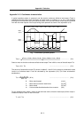
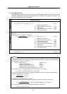
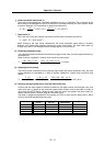
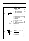
Appendix 2-3-1 Motor selection calculation
Servomoto
r
Deceleration ratio = 2/3
500kg
10kg
Primary side
gear
1.6kg·cm
2
Ball screw
Ø50, 1000mm
Fig. 11-3 Z axis configuration
Secondary
side gear
8.1kg·cm
2
The selection calculation is
carried out in order using the Z axis as
an example.
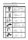
(1) Obtaining the load inertia
Calculate the motor shaft conversion load inertia separately
for the rotation load and linear movement load. Furthermore,
calculate the rotation load inertia separately for the primary
and secondary side.
Primary side rotation load inertia: J
R1
This is the primary side gear inertia.
J
R1 = 1.6 (kg
.
cm
2
)
Secondary side rotation load inertia: J
R2
This is the sum of the ball screw inertia J
B and secondary side gear inertia. The ball screw is
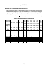
generally calculated as a cylinder made of steel. Refer to section "Appendix 2-5 Expressions for
load inertia calculation".
J
R2 = JB + 8.1 =
· · L
32
D
4
+ 8.1 =
7.80 10
3
100
32
5
4
+ 8.1
= 47.9 + 8.1 = 56.0 (kg
.
cm
2
)
Total rotation load inertia: J
R
This is the sum of the primary side load inertia and secondary side load inertia. To convert the
secondary side load inertia to the motor shaft (primary side), multiply by the square of the
deceleration ratio.
J
R = JR1 + (
2
3
)
2
JR2 = 1.6 +
4
9
56.0 = 1.6 + 24.9 = 26.5 (kg
.
cm
2
)