


Appendix 4. EMC Installation Guidelines
A4 - 5
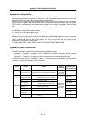
Appendix 4-5 Measures for various cables
The various cables act as antennas for the noise and discharge the noise externally. Thus appropriate
treatment is required to avoid the noise.
The wiring between the drive unit and motor act as an extremely powerful noise source, so apply the
following measures.
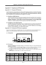
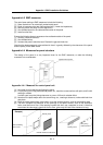
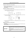
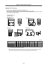
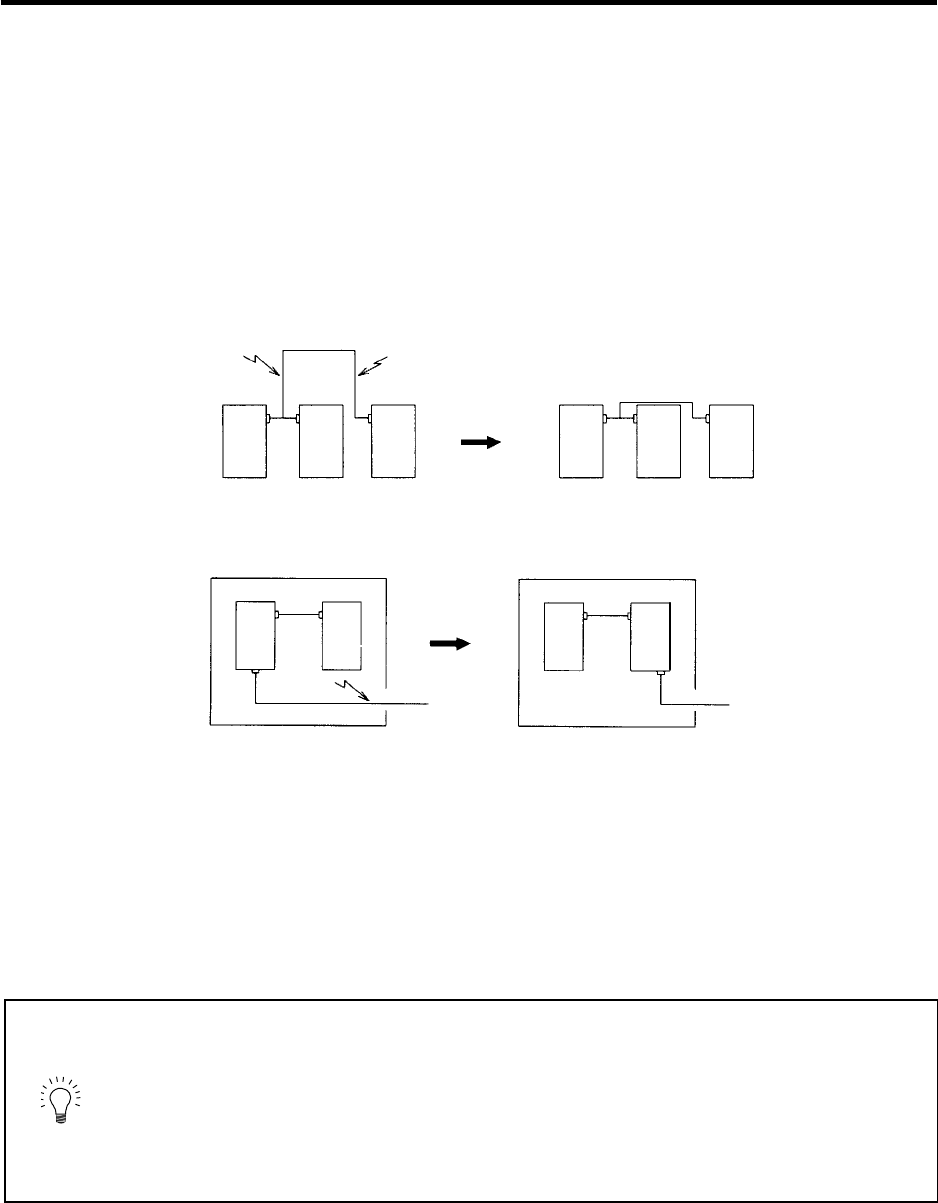
Appendix 4-5-1 Measures for wiring in panel
[1] If the cables are led unnecessarily in the panel, they will easily pick up the radiated noise. Thus,
keep the wiring length as short as possible.
Device Device Device Device Device Device
Noise Noise
[2] The noise from other devices will enter the cable and be discharged externally, so avoid internal
wiring near the openings.
Device
Device
Device
Device
Noise
Control panel
Control panel
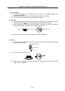
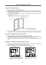
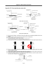
[3] Connect the control device earthing terminal and earthing plate with a thick wire. Take care to the
leading of the wire.
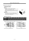
Appendix 4-5-2 Measures for shield treatment
Common items
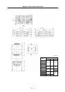
Use of shield clamp fittings is recommended for treating the shields. The fittings are available as options,
so order as required.
Clamp the shield at a position within 10cm from the panel lead out port.
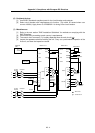
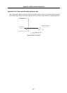
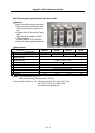
POINT
1. When leading the cables, including the grounding wire (FG), outside of the
panel, clamp the cables near the panel outlet (recommendation: within
10cm).
2. When using a metal duct or conduit, the cables do not need to be clamped
near the panel outlet.
3. When leading cables not having shields outside the panel, follow the
instructions given for each cable. (Installation of a ferrite core, etc., may be
required.)