


3. Characteristics
3 - 7
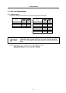
3-2 Servomotor
3-2-1 Shaft characteristics
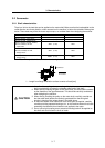
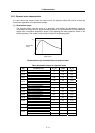
There is a limit to the load that can be applied on the motor shaft. Make sure that the load applied on the
radial direction and thrust direction, when mounted on the machine, is below the tolerable values given
below. These loads may affect the motor output torque, so consider them when designing the machine.
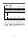
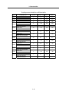
Servo motor Tolerable radial load Tolerable thrust load
HF75T, HF105T(Taper shaft)
245N (L=33) 147N
HF75S, HF105S(Straight shaft)
245N (L=33) 147N
HF54T, HF104T, HF154T, HF224T,
HF123T, HF223T, HF142T
(Taper shaft)
392N (L=58) 490N
HF54S, HF104S, HF154S, HF224S,
HF123S, HF223S, HF142S
(Straight shaft)
980N (L=55) 490N
HF204S, HF354S, HF303S, HF302S
(Straight shaft)
2058N (L=79) 980N
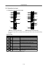
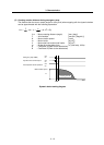
Note: The symbols in the table follow the drawing below.
L
Thrust load
Radial load
L : Length from flange installation surface to center of load [mm]
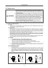
CAUTION
1. Use a flexible coupling when connecting with a ball screw, etc., and keep the
shaft core deviation to below the tolerable radial load of the shaft.
2. When directly installing the gear on the motor shaft, the radial load increases
as the diameter of the gear decreases. This should be carefully considered
when designing the machine.
3. When directly installing the pulley on the motor shaft, carefully consider so
that the radial load (double the tension) generated from the timing belt
tension is less than the values shown in the table above.
4. In machines where thrust loads such as a worm gear are applied, carefully
consider providing separate bearings, etc., on the machine side so that loads
exceeding the tolerable thrust loads are not applied to the motor.
5. Do not use a rigid coupling as an excessive bending load will be applied on
the shaft and could cause the shaft to break.