


Appendix 2. Selection
A2 - 16
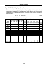
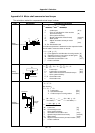
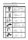
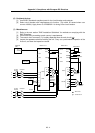
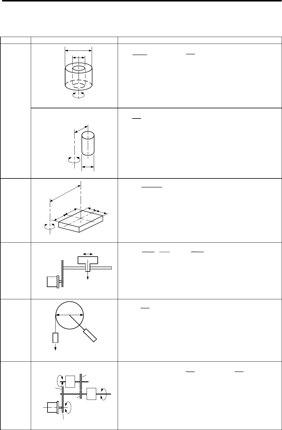
Appendix 2-5 Expressions for load inertia calculation
The calculation method for a representative load inertia is shown.
Type Mechanism Calculation expression
Rotary shaft
ØD1.
ØD2.
J
L =
.
(D
1
4
- D
2
4
) =
.
(D
1
2
- D
2
2
)
··L
Cylinder
When rota
ry shaft and cylinder
shaft are deviated
D
Rotary shaft
R
J
L =
.
(D
2
+ 8R
2
)
Column
a
a
b
b
Rotary shaft
R
J
L = W ( + R
2
)
Object that
moves
linearly
W
V
N
Servomotor
J
L = W ( · )
2
= W ( )
2
Suspended
object
D
W
J
L = W ( )
2
+ JP
Converted
load
Servomotor
Load A
J
A
N2
N1
N1
J11
J21
J31
Load B
J
B
N3
J22
J
L = J
11
+ (J
21
+ J
22
+ J
A
) ·( )
2
+ (J
31
+ J
B
) · ( )
2
W
8
JL : Load inertia [kg
.
cm
2
]
W : Mass of cylinder [kg]
D : Outer diameter of cylinder [cm]
R : Distance between rotary axis and
cylinder axis [cm]
a
2
+ b
2
3
JL : Load inertia [kg
.
cm
2
]
W : Mass of cylinder [kg]
a.b.R : Left diagram [cm]
N
3
N
1
N
2
N
1
JL : Load inertia [kg
.
cm
2
]
J
A,JB : Inertia of load A, B [kg
.
cm
2
]
J
11
~J
31
: Inertia [kg
.
cm
2
]
N
1
~N
3
: Each shaft’s speed [r/min]
J
L : Load inertia [kg
.
cm
2
]
W : Mass of object that moves linearly [kg]
N : Motor speed [r/min]
V : Speed of object that moves linearly [mm/min]
∆S:Ob
j
ect movement amount
p
er motor rotation
[
mm
]
V
10
1
2
N
∆S
20
D
2
JL : Load inertia [kg
.
cm
2
]
W : Object mass [kg]
D : Diameter of pulley [cm]
J
P : Inertia of pulley [kg
.
cm
2
]
32
W
Rotary
sha
ft is
cylinder
center
8
Reference data
JL : Load inertia [kg
.
cm
2
]
Material densities
: Density of cylinder material [kg
.
cm
3
]
Iron
..... 7.80
10
–3
[kg/cm
3
]
L :
Length of cylinder [cm]
Aluminum
D
1
: Outer diameter of cylinder [cm]
.....
2.70
10
–3
[kg/cm
3
]
D
2
: Inner diameter of cylinder [cm]
Copper
W :
Mass of cylinder [kg]
.....
8.96
10
–3
[kg/cm
3
]