


Appendix 4. EMC Installation Guidelines
A4 - 6
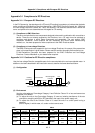
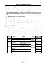
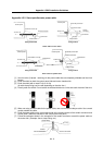
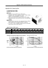
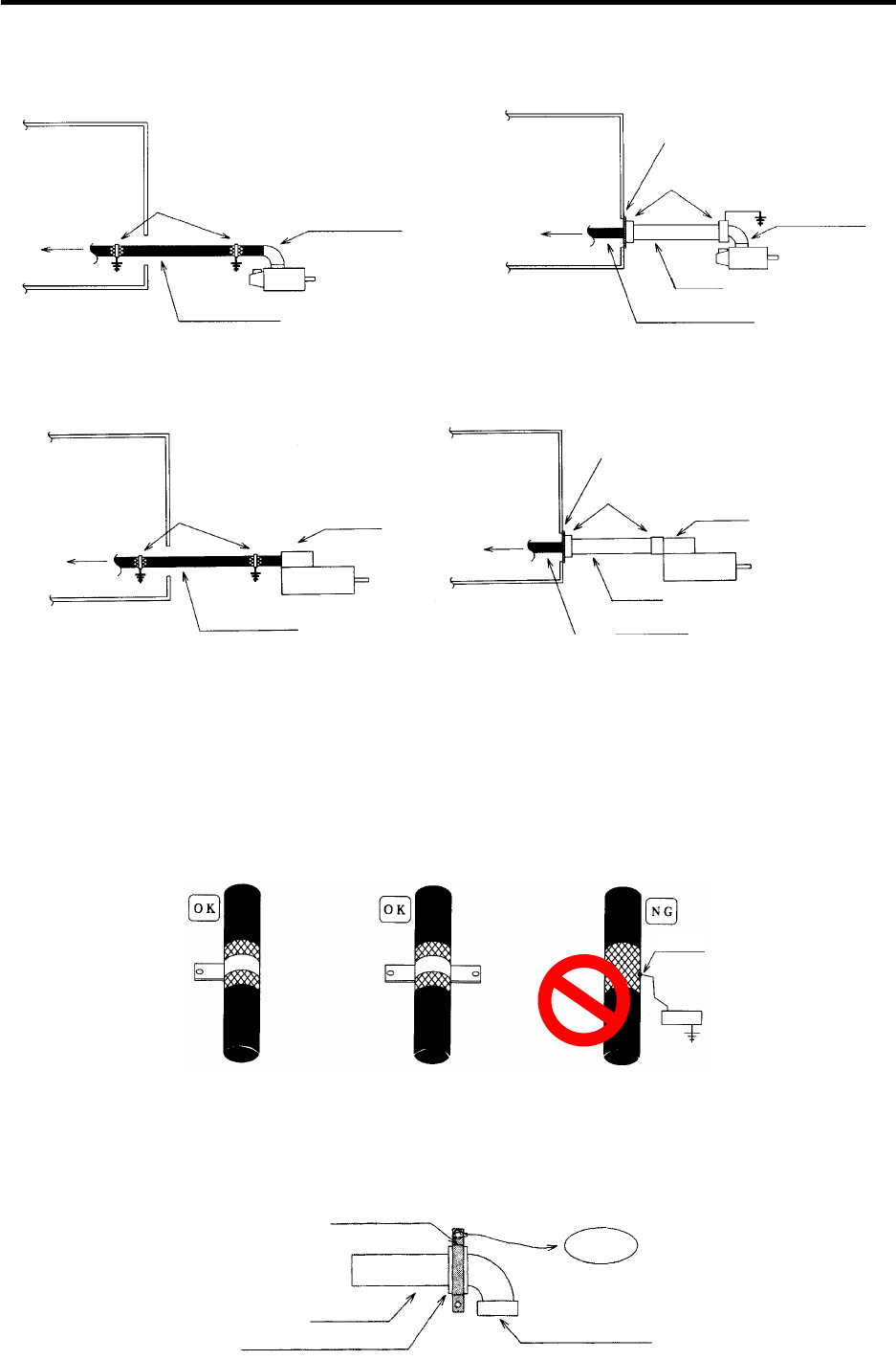
Appendix 4-5-3 Servo/spindle motor power cable
Control panel
To drive unit
Earth with P or U clip
Shield cable
Cannon connector
Servomotor
Control panel
To drive unit
Cannon
connector
Servomotor
Earth with paint mask
Conduit connecto
r
Conduit
Cabtyre cable
Using shield cable Using conduit
Power cable for servo motor
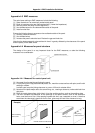
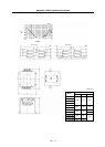
Control panel
Control panel
To drive unit
Earth with P or U clip
Shield cable
Terminal box
Servo motor
To drive unit
Cabtyre cable
Conduit
Earth with paint mask
Conduit connector
Terminal box
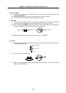
Using shield cable Using conduit
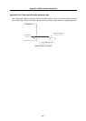
Power cable for spindle motor
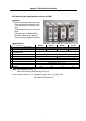
[1] Use four wires (3-phase + earthing) for the power cable that are completely shielded and free from
breaks.
[2] Earth the shield on both the control panel side and motor chassis side.
[3] Earth the shield with a metal P clip or U clip.
(A cable clamp fitting can be used depending on the wire size.)
[4] Directly earth the shield. Do not solder the braided shield onto a wire and earth the end of the wire.
[5] When not using a shield cable for the power cable, use a conventional cabtyre cable. Use a metal
conduit outside the cable.
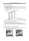
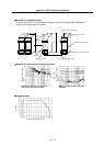
Solder
[6]
Earth the power cable on the control panel side at the contact surface of the conduit connector and
control panel. (Mask the side wall of the control panel with paint.)
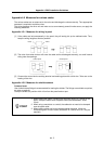
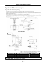
[7]
Follow the treatment shown in the example for the conduit connector to earth the power cable on
the motor side. (Example: Use a clamp fitting, etc.)
Cannon connector
Conduit connector
Conduit
To earthing
Clamp fitting