


Appendix 5 Instruction Manual for Compliance with UL/c-UL Standard
A5 - 2
Instruction Manual for Compliance with UL/c-UL Standard
(MDS-R Series)
The instructions of UL/c-UL listed products are described in this manual.
The descriptions of this manual are conditions to meet the UL/c-UL
standard for the UL/c-UL listed products. To obtain the best performance,
be sure to read this manual carefully before use.
To ensure proper use, be sure to read specification manual, connection
manual and maintenance manual carefully for each product before use.
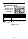
Appendix 5-1 Operation surrounding air ambient
temperature
The recognized operation ambient temperatures of each unit are as
shown in the table below. The recognized operation ambient
temperatures are the same as an original product specification for all of
the units.
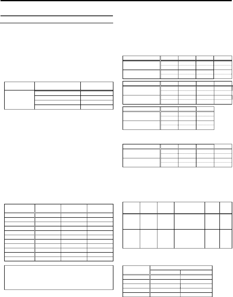
Classification Unit name
Operation ambient
temperature
Power supply unit
0~55C
Servo, Spindle drive unit
0~55C
Option unit, Battery unit
0~55C
AC Servo/
Spindle system
Servo motor, Spindle motor
0~40C
Appendix 5-2 Notes for AC servo system
Appendix 5-2-1 General Precaution
It takes 10 minutes to discharge the bus capacitor.
When starting wiring or inspection, shut the power off and wait for more
than 15 minutes to avoid a hazard of electrical shock.
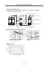
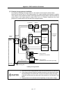
Appendix 5-2-2 Installation
MDS-R Serie
s
have been approved as the products which have been
installed in the electrical enclosure.
The minimum enclosure size is based on 150 percent of each MDS-R
Series combination. And also, design the enclosure so that the ambient
temperature in the enclosure is 55C (131F) or less, refer to the
specifications manual.
Appendix 5-2-3 Short-circuit ratings
Suit
able
for use in a circuit capable of delivering not more than 100 kA
rms symmetrical amperes, 500 volts maximum.
Appendix 5-2-4 Peripheral devices
To comply
w
ith UL/c-UL Standard, use the peripheral devices which
conform to the corresponding standard.
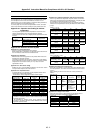
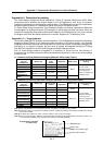
- Circuit Breaker, Fuses, Magnetic Contactor and AC Reactor
Applicable
power supply unit
Circuit Breaker
Fuse
Class K5
Magnetic
Contactor (AC3)
MDS-R-V1-20 NF30 15A 30A S-N12
MDS-R-V1-40 NF30 20A 40A S-N18
MDS-R-V1-60 NF30 30A 60A S-N20
MDS-R-V1-80 NF30 30A 60A S-N25
MDS-R-V2-2020 NF30 20A 40A S-N18
MDS-R-V2-4040 NF30 30A 60A S-N20
MDS-R-V2-6040 NF30 30A 80A S-N20
MDS-R-V2-6060 NF50 40A 80A S-N25
MDS-R-V2-8040 NF50 40A 80A S-N25
MDS-R-V2-8060 NF50 40A 80A S-N25
MDS-R-V2-8080 NF50 40A 80A S-N25
<Notice>
- For installation in United States, branch circuit protection must be
provided, in accordance with the National Electrical Code and any
applicable local codes.
- For installation in Canada, branch circuit protection must be
provided, in accordance with the Canadian Electrical Code and any
applicable provincial codes.
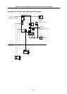
Appendix 5-2-5 Field Wiring Reference Table for Input and Output
Use the Tyco Electronics Corporation "Dynamic Series" connectors to
wire the input and output terminals of MDS-R Series. Crimp the pins with
the crimping tool recommended by the manufacturer.
This wire size is each unit maximum rating. The selection method is
indicated in each specification manual. (See Manual: No. BNP-C3045)
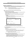
(1) Input
CN30 (L1, L2, L3)
Capacity [kW] 20 40 60 80
Wire Size (AWG)
/Temp Rating Note 1
#14/75C #14/75C #12/75C #12/75C
Earth Wire Size
(AWG)
#14/75C #14/75C #12/75C #12/75C
Capacity [kW] 2020 4040 6040 6060
Wire Size (AWG)
/Temp Rating Note 1
#14/75C #14/75C #12/75C #12/75C
Earth Wire Size
(AWG)
#14/75C #14/75C #12/75C #12/75C
Capacity [kW] 8040 8060 8080
Wire Size (AWG)
/Temp Rating Note 1
#12/75C #10/75C #10/75C
Earth Wire Size
(AWG)
#12/75C #10/75C #10/75C
(2) Output
CN31L, CN31M (U, V, W)
Capacity [kW] 20 40 60 80
Wire Size (AWG)
/Temp Rating Note 1
#14/75C #14/75C #12/75C #12/75C
Earth Wire Size
(AWG)
#14/75C #14/75C #12/75C #12/75C
Appendix 5-2-6 Motor Over Load Protection
Servo driv
e unit MDS-R-V1 and V2 series have each solid-state motor
over load protection.
(The motor full load current is the same as rated
current.)
When adjusting the level of motor over load, set the parameter as
follows.
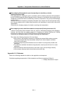
MDS-R-V1/V2
Parameter
No.
Parameter
abbr.
Parameter
name
Setting
Procedure
Standard
setting
value
Setting
range
SV021 OLT Overload
time
constant
Set the time
constant for
overload detection.
(Unit: 1 second.)
60s 1 to
300s
SV022 OLL Overload
detection
level
Set the overload
current detection
level with a
percentage (%) of
the stall rating.
150% 1 to
500%
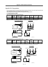
Appendix 5-2-7 Flange of servo motor
Mount the
servo motor on a flange which has the following size or
produces an equivalent or higher heat dissipation effect:
Servo Motor
Flange size
(mm)
HF, HC HC-MF, HA-FF
150x150x6 --- <100 W
250x250x6 --- 200, 300 W
250x250x12 0.5 to 1.5 kW 400, 600 W
300x300x12 --- 750 W
300x300x20 2.0 to 3.5 kW ---