


8. Setup
8 - 18
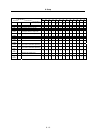
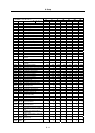
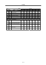
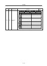
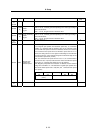
No. Abbrev. Parameter name Explanation
Setting
range (Unit)
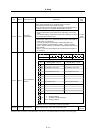
SV032 TOF Torque offset 1
Set the unbalance torque of vertical axis and slant axis. -100 to 100
(Stall
current %)
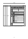
FEDCBA98765 4 3 2 10
zup dis nfd2 nf3 nfd1
bit Meaning when "0" is set Meaning when "1" is set
0
1 Set the filter depth for Notch filter 1 (SV038).
2 nfd1 Value 000 001 010 011 100 101 110 111
3
Depth (dB)
Deep
-
∞
-18.1 -12.0 -8.5 -6.0 -4.1 -2.5 -1.2
Shallow
4 nf3 Notch filter 3 stop Notch filter 3 start (1125Hz)
5 Set the operation frequency of Notch filter 2 (SV046).
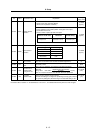
6 nfd2 Value 000 001 010 011 100 101 110 111
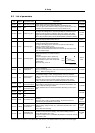
SV033 SSF2
Servo function
selection 2
7
Depth (dB)
Deep
-
∞
-18.1 -12.0 -8.5 -6.0 -4.1 -2.5 -1.2
Shallow
8
9
A
B
dis
Select the digital signal input.
00: DI not used 10: Reserved
01: Contactor B contact input 11: Reserved
C
D
E zup Vertical axis pull up control stop Vertical axis pull up control start
F
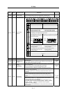
(Note) Set to "0" for bits with no particular description.
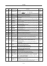
FEDCBA98765 4 3 2 10
ovsn zeg
bit Meaning when "0" is set Meaning when "1" is set
0
1
2
3
4
SV034 SSF3 Servo function
5zeg
Z phase normal edge detection
(Setting for normal use)
Z phase reverse edge detection
(Valid only when SV027/bit6=1)
selection 3 6os2
Setting for normal use Overspeed detection level
changeover
7
8
9
A
B
C
D
E
F
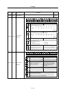
ovsn
Set the non-sensitive band of the overshooting compensation type 3 in
increments of 2µm at a time.
In the feed forward control, the non-sensitive band of the model
position droop is set, and overshooting of the model is ignored.
Set the same value as the standard SV040.
(Note) Set to "0" for bits with no particular description.