


8. Setup
8 - 7
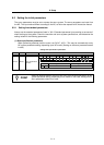
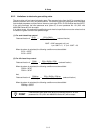
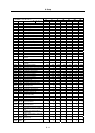
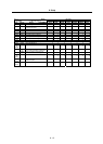
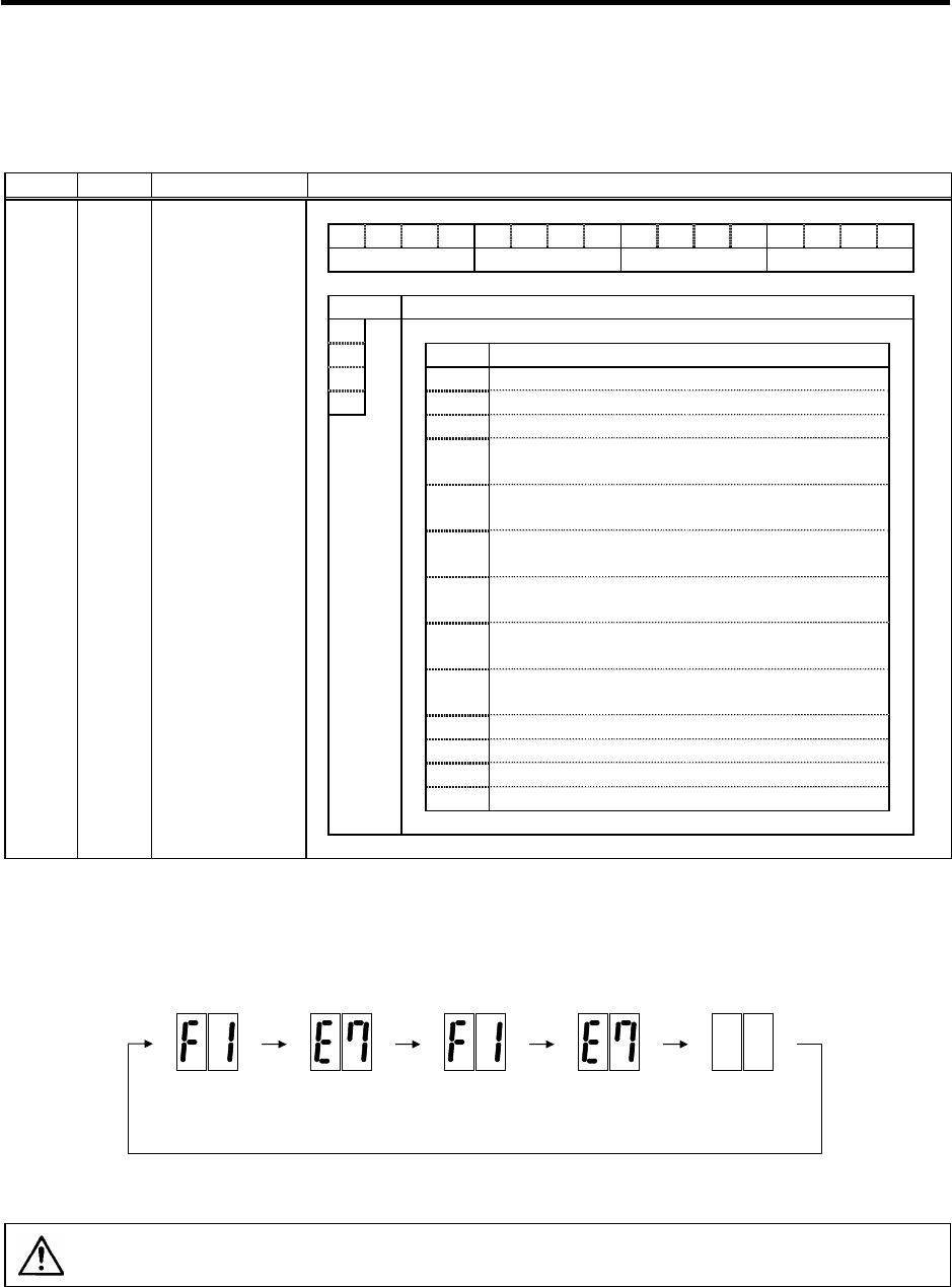
(4) Setting of regenerative resistor type
Set the following parameter according to the connected regenerative resistor unit.
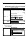
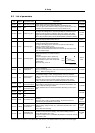
No. Abbrev. Parameter name Explanation
F E D C B A 9 8 7 6 5 4 3 2 1 0
1 rtyp emgx 0
bit Explanation
8 Set the regenerative resistor type.
9 Setting Details
A
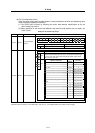
rtyp
0 to 1 Setting prohibited
B 2 GZG200W26OHMJ
3 GZG300W20OHMJ
4
MR-RB32 or GZG200W120OHMJ 3 units connected
in parallel
5
MR-RB30 or GZG200W39OHMJ 3 units connected in
parallel
6
MR-RB50 or GZG300W39OHMJ 3 units connected in
parallel
7
MR-RB31 or GZG200W20OHMJ 3 units connected in
parallel
8
MR-RB51 or GZG300W20OHMJ 3 units connected in
parallel
9
MR-RB65 or GRZG400-2OHMJ 4 units connected in
serial
A GZG80W26OHMJ
B GZG400W13OHMJ
C GZG400W8OHMJ
D to F Setting prohibited
SV036 PTYP*
Regenerative
resistor type
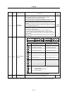
Parameters with an asterisk * in the abbreviation, such as PC1*, are validated with the NC power turned ON again.
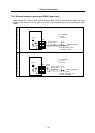
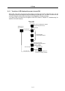
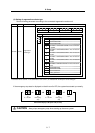
If the emergency stop state is displayed on the drive unit's LED, the system has started up normally.
OFF
F1 E7 F1 E7
F + axis No. F + axis
No.
Emergency
stop
Emergency
stop
Normal LED disp
lay at NC power ON (1st axis)
CAUTION
Always input emergency stop when starting up the servo system.