


6. Installation
6 - 11
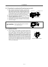
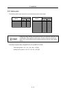
6-2-6 Heat radiation countermeasures
(1) Heat radiation countermeasures in the control panel
In order to secure reliability and life, design the temperature in the panel so that the ambient
temperature of each unit is 55°C or less.
If the heat accumulates at the top of the unit, etc., install a fan or heat exchanger so that the
temperature in the panel remains constant.
Please refer to following method for heat radiation countermeasures.
<Point>
[1] Refer to the section “6-5 Heating value” for the heat
generated by each unit.
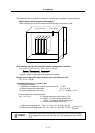
[2] Refer to the following calculation for calculation W1 of the
panel’s cooling capacity (thin steel plate).
W1 = U x A x
ΔT
U: 6W/m
2
x °C (with internal agitating fan)
4W/m
2
x °C (without internal agitating fan)
A: Effective heat radiation area [m
2
]
(Heat dissipation area in panel)
Sections contacting other objects are excluded.
T: Internal temperature rise value (10°C)
[3] Points in manufacturing and evaluation
Understanding the temperature rise in the panel, and
install a fan or heat exchanger.
T (average value) 10°C
T
max
(maximum value) 15°C
<Hypothetical conditions>
[1] Average temperature in panel: T
55°C
[2] Panel peripheral temperature: Ta
0 to 45°C
[3] Internal temperature rise value:
T=T-Ta
max
=10°C
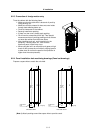
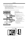
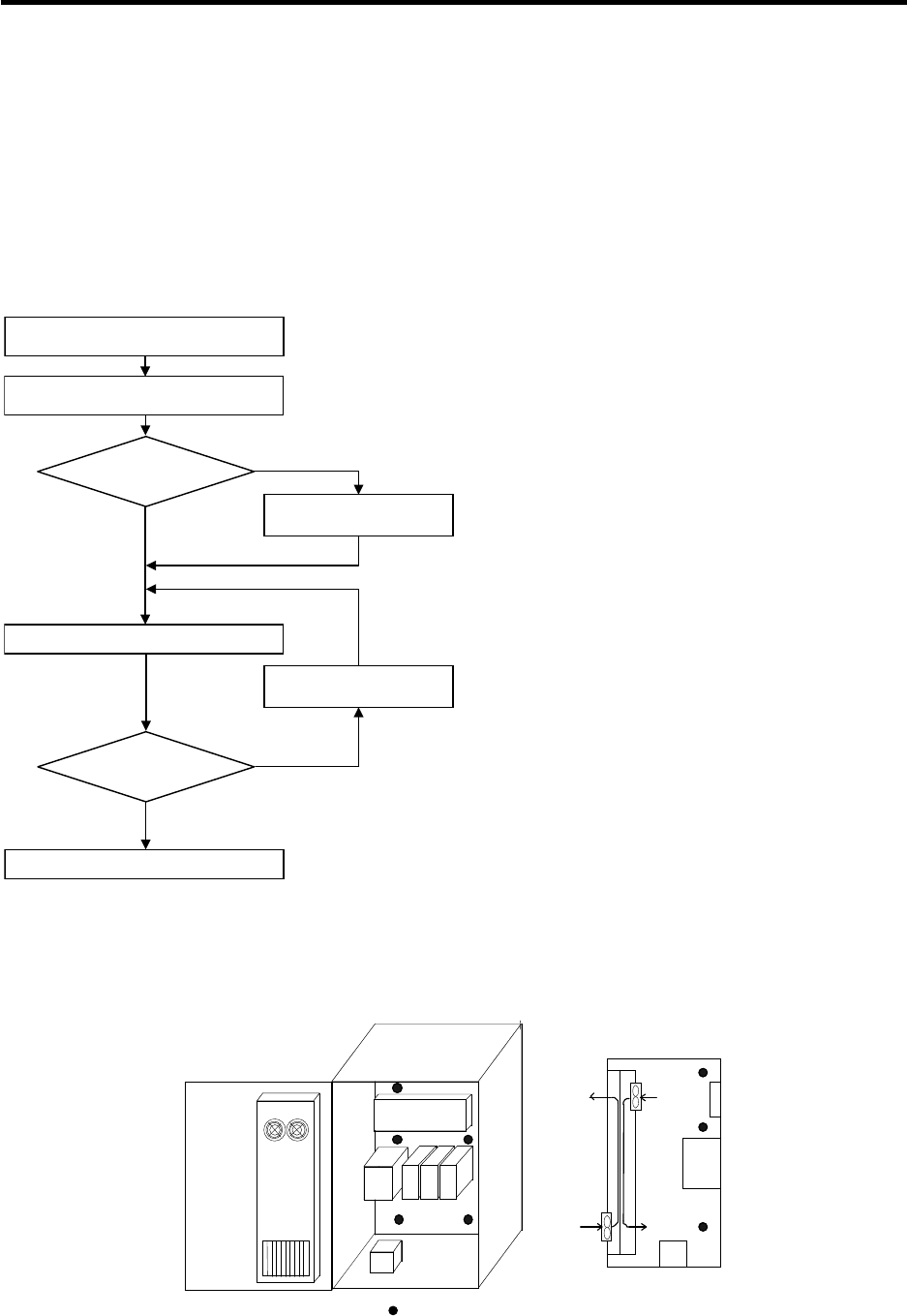
Calculate total heat radiation of each
unit in panel (W)
Manufacturing and evaluation
W
W1
W>W1
ΔT > 10℃
ΔT 10℃
Completion
Evaluate temperature
in panel
Comparison of
W and W1
Calculate panel’s cooling capacity
(W1)
Consider heat
exchanger
Consider adding fan or
heat exchanger
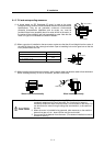
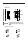
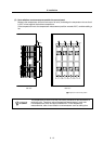
Examples of mounting heat exchanger and temperature measurement positions (reference)
Temperature measurement positions
Heat
exchanger
Heat
exchanger
Unit
Relay, etc
Unit
Flow of air
Flow of air
Relay, etc