


6-1-5 Oil and waterproofing measures................................................................................................ 6-4
6-1-6 Cable stress............................................................................................................................... 6-5
6-2 Installation of the units.............................................................................................................................6-6
6-2-1 Environmental conditions........................................................................................................... 6-6
6-2-2 Installation direction and clearance ........................................................................................... 6-7
6-2-3 Prevention of foreign matter entry ............................................................................................. 6-9
6-2-4 Panel installation hole machining drawings (Panel cut drawings)............................................. 6-9
6-2-5 Heating value........................................................................................................................... 6-10
6-2-6 Heat radiation countermeasures.............................................................................................. 6-11
6-3 Noise measures.....................................................................................................................................6-14
7. Wiring and Connection
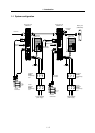
7-1 Part system connection diagram.............................................................................................................7-3
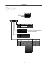
7-2 Main circuit and control circuit connectors..............................................................................................7-4
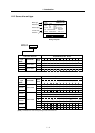
7-2-1 Connector pin assignment ......................................................................................................... 7-4
7-2-2 Main circuit and control circuit connector signal names and applications................................. 7-5
7-3 NC and drive unit connection ..................................................................................................................7-6
7-4 Motor and detector connection................................................................................................................7-7
7-4-1 Connection of servomotor HF Series......................................................................................... 7-7
7-5 Connection of main circuit power supply ..............................................................................................7-10
7-6 Connection of regenerative resistor ......................................................................................................7-11
7-6-1 Connection of external option regeneration resistance unit .................................................... 7-11
7-6-2 Connection of external regenerative resistor........................................................................... 7-12
7-7 Wiring of contactors...............................................................................................................................7-14
7-7-1 Contactor control...................................................................................................................... 7-14
7-7-2 Contactor control signal (MC) output circuit.............................................................................7-15
7-7-3 Contactor power ON sequences.............................................................................................. 7-16
7-7-4 Contactor shutoff sequences................................................................................................... 7-16
7-7-5 Monitor of contactor operation................................................................................................. 7-17
7-8 Wiring of the motor brake ......................................................................................................................7-18
7-8-1 Motor brake control signal (MBR) output circuit ...................................................................... 7-18
7-8-2 Motor brake release sequence ................................................................................................ 7-19
7-8-3 Control during the servo OFF command ................................................................................. 7-19
7-8-4 Operation sequences when an emergency stop occurs.......................................................... 7-19
7-9 Wiring of an external emergency stop ..................................................................................................7-20
7-9-1 External emergency stop setting ............................................................................................. 7-20
7-9-2 External emergency stop signal (EMGX) input circuit ............................................................. 7-21
7-9-3 External emergency stop operation sequence ........................................................................ 7-22
8. Setup
8-1 Servo drive unit initial settings.................................................................................................................8-2
8-1-1 Setting the rotary switch ............................................................................................................ 8-2
8-1-2 Transition of LED display after power is turned ON .................................................................. 8-3
8-2 Setting the initial parameters...................................................................................................................8-4
8-2-1 Setting the standard parameters ............................................................................................... 8-4
8-2-2 Limitations to electronic gear setting value................................................................................ 8-8
8-2-3 Standard parameter list according to servomotor...................................................................... 8-9
8-3 List of parameters ..................................................................................................................................8-13
9. Adjustment
9-1 Servo adjustment data output function (D/A output) ..............................................................................9-2
9-1-1 D/A output specifications ........................................................................................................... 9-2
9-1-2 Setting the output data............................................................................................................... 9-2
9-1-3 Setting the output magnification ................................................................................................ 9-3
9-1-4 Current feedback analog output function................................................................................... 9-3
9-2 Gain adjustment.......................................................................................................................................9-4
9-2-1 Current loop gain ....................................................................................................................... 9-4
9-2-2 Speed loop gain......................................................................................................................... 9-4
9-2-3 Position loop gain....................................................................................................................... 9-7
9-3 Characteristics improvement...................................................................................................................9-9
9-3-1 Optimal adjustment of cycle time............................................................................................... 9-9
9-3-2 Vibration suppression measures ............................................................................................. 9-12
9-3-3 Improving the cutting surface precision ................................................................................... 9-16