


4. Dedicated Options
4 - 13
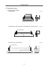
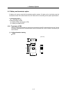
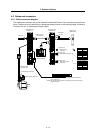
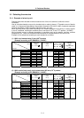
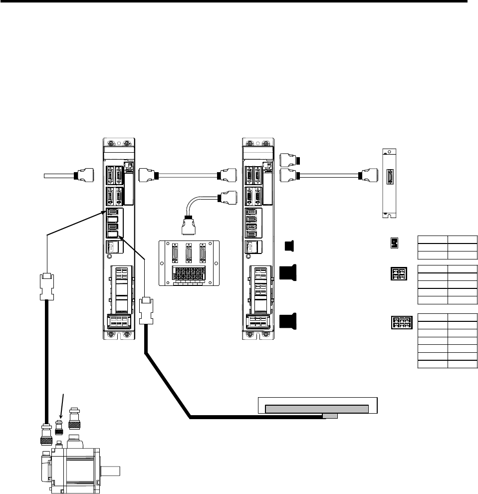
4-5 Cables and connectors
4-5-1 Cable connection diagram
The cables and connectors that can be ordered from Mitsubishi Electric Corp. as option parts are shown
below. Cables can only be ordered in the designated lengths shown on the following pages. Purchase a
connector set, etc., to create special length cables.
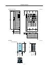
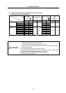
Servo drive unit
(MDS-R-V1)
From NC
Battery unit
(MDS-A-BT)
Terminator
(A-TM)
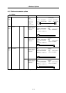
(3) Motor power connector
(4) Motor brake connector
(2) Detector cable
connector set
(1) NC bus cable
connector set
(1)
Servomotor
(1)
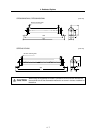
Servo drive unit
(MDS-R-V2)
(6) Drive unit
Motor power connector
(5) Drive unit
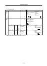
Main circuit power
connector
(1)
(7) Drive unit
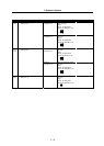
Control power
connector
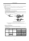
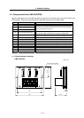
Relay terminal block
(MR-J2CN3TM)
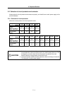
1
2
B
A
1 2
Pin No. Signal
A1 V
A2 PE
B1 U
B2 W
B
A
1 2 3
Pin No. Signal
A1 P
A2 C
A3 PE
B1 L1
B2 L2
B3 L3
Pin No. Signal
1 VDD
2 SG
(Note1) The compatible linear scale is a relative position rectangular
wave output type.
(Note2) The linear scale and cable for connecting a linear scale must be
prepared by user.