


Appendix 4. EMC Installation Guidelines
A4 - 3
Appendix 4-3 EMC measures
The main items relating to EMC measures include the following.
[1] Store the device in an electrically sealed metal panel.
[2] Earth all conductors that are floating electrically. (Lower the impedance.)
[3] Wire the power line away from the signal wire.
[4] Use shielded wires for the cables wired outside of the panel.
[5] Install a noise filter.
Ensure the following items to suppress noise radiated outside of the panel.
[1] Securely install the devices.
[2] Use shielded wires.
[3] Increase the panel's electrical seal. Reduce the gap and hole size.
Note that the electromagnetic noise radiated in the air is greatly affected by the clearance of the panel
and the quality of the cable shield.
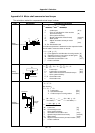
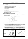
Appendix 4-4 Measures for panel structure
The design of the panel is a very important factor for the EMC measures, so take the following
measures into consideration.
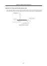
Door
Control panel
Operation board panel
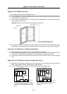
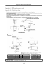
Appendix 4-4-1 Measures for control panel unit
[1] Use metal for all materials configuring the panel.
[2] For the joining of the top plate and side plates, etc., mask the contact surface with paint, and fix with
welding or screws.
In either case, keep the joining clearance to a max. of 20cm for a better effect.
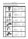
[3] Note that if the plate warps due to the screw fixing, etc., creating a clearance, noise could leak from
that place.
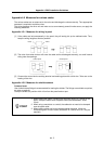
[4] Plate the metal plate surface (with nickel, tin) at the earthing section, such as the earthing plate.
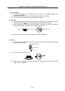
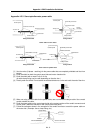
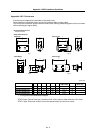
[5] The max. tolerable hole diameter of the openings on the panel surface, such as the ventilation
holes, must be 3cm to 5cm. If the opening exceeds this size, use a measure to cover it. Note that
even when the clearance is less than 3cm to 5cm, noise may still leak if the clearance is long.
Painting mask
Hole exceeding
3cm to 5cm
Provide electrical conductance
Painting mask
Max. joining
clearance 20cm
Exam
p
le
)