


2. Specifications
2 - 54
2-2-4 Explanation of each part
(1) Explanation of each servo drive unit part
<4>
<5>
<8>
<6>
<1>
<2>
<16>
<12>
<14>
<13>
<3>
<10>
<7>
<9>
<4>
<5>
<8>
<7>
<6>
<1>
<2>
<15>
<16>
<12>
<14>
<13>
<3>
<10>
<11>
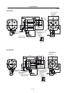
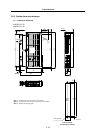
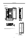
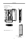
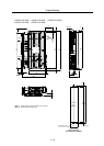
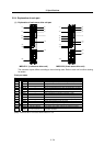
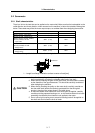
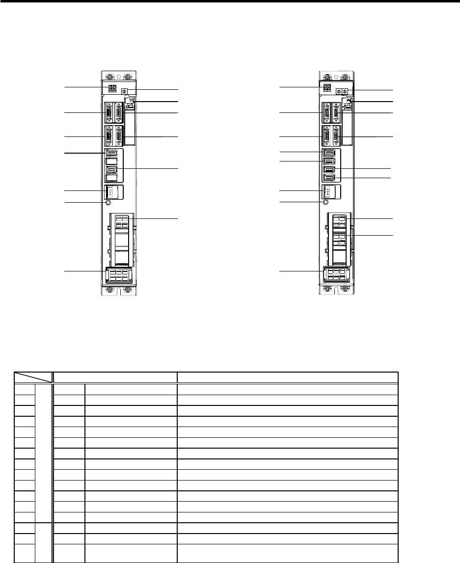
MDS-R-V1 (1-axis servo drive unit) MDS-R-V2 (2-axis servo drive unit)
The connector layout differs according to the unit being used. Refer to each unit’s outline drawing
for details.
Each part name
Name Description
<1> LED --- Unit status indication LED
<2> SW1 --- Axis No. setting switch (Left: L axis, Right: M axis)
<3> BT1A --- Battery connection connector
<4> CN1A --- NC or upward axis communication connector
<5> CN1B --- Battery unit/Terminator/Lower axis communication connector
<6> CN9 --- Analog output connector
<7> CN4 --- Maintenance connector
<8> CN2L --- Motor side detector connection connector (L axis)
<9> CN2M --- Motor side detector connection connector (M axis)
<10> CN3L --- Machine side detector connection connector (L-axis)
<11> CN3M --- Machine side detector connection connector (M-axis)
<12> CN22 --- Control power (24VDC) input connector
<13>
Control circuit
--- CHARGE LAMP Converter voltage output discharge status indication LED
<14> CN31L LU, LV, LW, PE L axis motor drive output (3-phase AC output) connector
<15> CN31M MU, MV, MW, PE M axis motor drive output (3-phase AC output) connector
<16>
Main
circuit
CN30 L1, L2, L3, PE, P, C
Power input (3-phase AC input), regenerative resistor
connection connector
(Note) CN2M/CN31M are not mounted with the MDS-R-V1 unit.