


7. Wiring and Connection
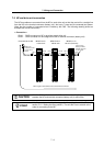
7-1 Part system connection diagram........................................................................................................ 7-3
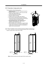
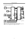
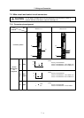
7-2 Main circuit and control circuit connectors......................................................................................... 7-4
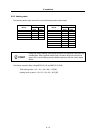
7-2-1 Connector pin assignment .......................................................................................................... 7-4
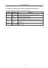
7-2-2 Main circuit and control circuit connector signal names and applications .................................. 7-5
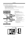
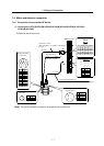
7-3 NC and drive unit connection............................................................................................................. 7-6
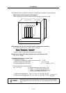
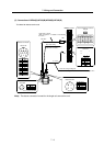
7-4 Motor and detector connection .......................................................................................................... 7-7
7-4-1 Connection of servomotor HF Series.......................................................................................... 7-7
7-5 Connection of main circuit power supply ......................................................................................... 7-10
7-6 Connection of regenerative resistor ................................................................................................. 7-11
7-6-1 Connection of external option regeneration resistance unit...................................................... 7-11
7-6-2 Connection of external regenerative resistor ............................................................................ 7-12
7-7 Wiring of contactors ......................................................................................................................... 7-14
7-7-1 Contactor control....................................................................................................................... 7-14
7-7-2 Contactor control signal (MC) output circuit.............................................................................. 7-15
7-7-3 Contactor power ON sequences............................................................................................... 7-16
7-7-4 Contactor shutoff sequences .................................................................................................... 7-16
7-7-5 Monitor of contactor operation .................................................................................................. 7-17
7-8 Wiring of the motor brake................................................................................................................. 7-18
7-8-1 Motor brake control signal (MBR) output circuit........................................................................ 7-18
7-8-2 Motor brake release sequence.................................................................................................. 7-19
7-8-3 Control during the servo OFF command................................................................................... 7-19
7-8-4 Operation sequences when an emergency stop occurs........................................................... 7-19
7-9 Wiring of an external emergency stop ............................................................................................. 7-20
7-9-1 External emergency stop setting............................................................................................... 7-20
7-9-2 External emergency stop signal (EMGX) input circuit............................................................... 7-21
7-9-3 External emergency stop operation sequence.......................................................................... 7-22
7 - 1