


Appendix 8 Old motor specifications
A8 - 21
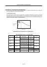
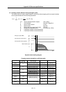
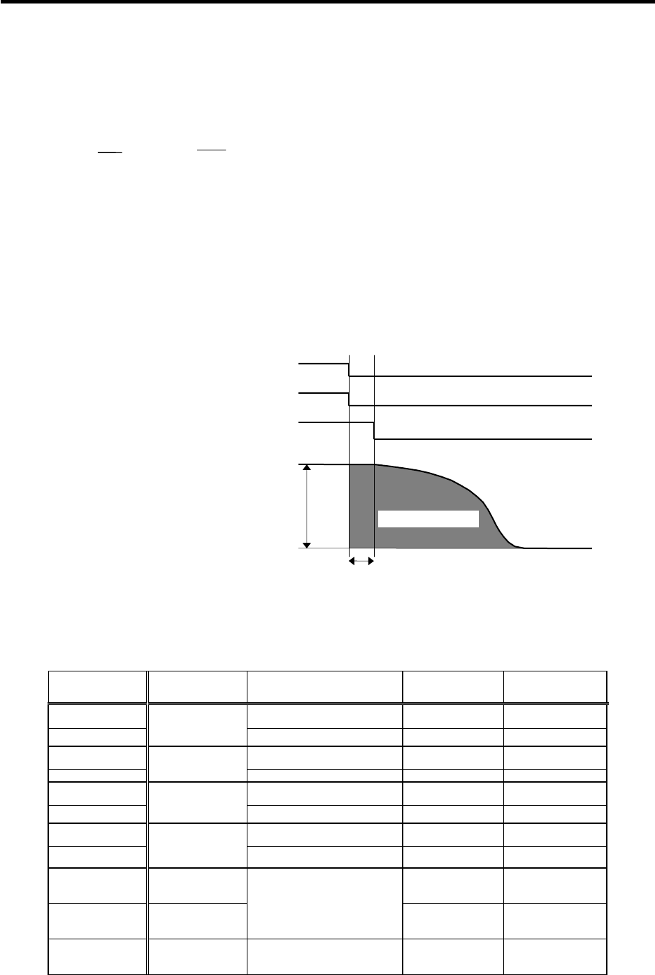
(2) Coasting rotation distance during emergency stop
The distance that the motor coasts (angle for rotary axis) when stopping with the dynamic brakes
can be approximated with the following expression.
L
MAX =
F
60
▪ {te + (1 +
J
L
J
M
) ▪ (A ▪ N
2
+ B)}
L
MAX : Motor coasting distance (angle) [mm, (deg)]
F
: Axis feedrate [mm/min, (deg/min)]
N : Motor rotation speed [r/min]
J
M : Motor inertia [kg
.
cm
2
]
J
L : Motor shaft conversion load inertia [kg
.
cm
2
]
te : Brake drive relay delay time (s) (Normally, 0.03s)
A : Coefficient A (Refer to the table below)
B : Coefficient B (Refer to the table below)
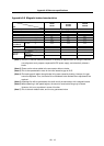
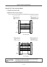
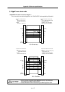
Dynamic brake braking diagram
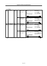
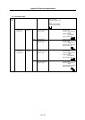
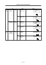
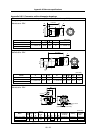
Coasting amount calculation coefficients table
Motor type
JM
(kg・cm
2
)
Combination
drive unit type
A B
HF44
MDS-R-V1-20 to 40
MDS-R-V2-2020 to 4040
0.67×10
-9
3.14×10
-3
2.6
MDS-R-V2-6040 to 8040 0.65×10
-9
3.21×10
-3
HF74
MDS-R-V1-20 to 40
MDS-R-V2-2020 to 4040
1.31×10
-9
6.16×10
-3
5.1
MDS-R-V2-6040 to 8040 1.20×10
-9
6.73×10
-3
HF53
MDS-R-V1-20 to 40
MDS-R-V2-2020 to 4040
5.62×10
-9
3.85×10
-3
6.1
MDS-R-V2-6040 to 8040 5.03×10
-9
4.30×10
-3
HF103
MDS-R-V1-20 to 40
MDS-R-V2-2020 to 4040
5.06×10
-9
2.54×10
-3
11.9
MDS-R-V2-6040 to 8040 3.84×10
-9
3.35×10
-3
HF153 17.8 3.68×10
-9
3.23×10
-3
HF203 38.3
MDS-R-V1-60 to 80
MDS-R-V2-6040 to 8080
11.41×10
-9
4.62×10
-3
HF353 75.0
MDS-R-V1-60 to 80
MDS-R-V2-6060 to 8080
8.00×10
-9
5.17×10
-3
te
OFF
ON
Emergency stop (EMG)
Actual dynamic brake operation
N
Time
Motor rotation speed
Dynamic brake control output
OFF
ON
Coasting amount
OFF
ON