


9. Adjustment
9 - 19
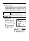
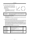
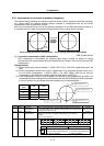
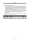
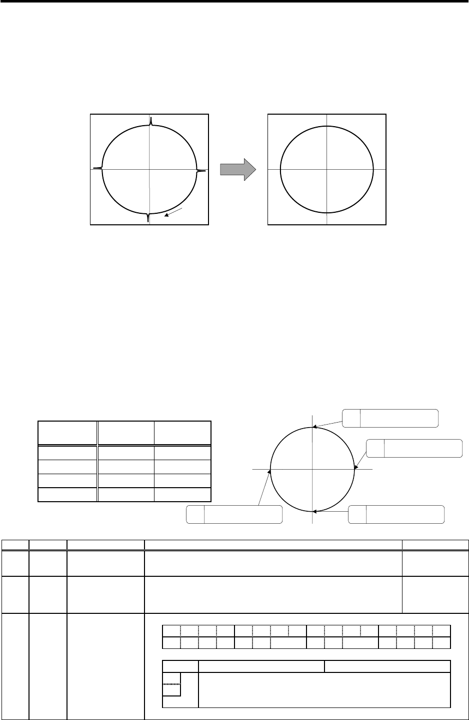
9-3-4 Improvement of protrusion at quadrant changeover
The response delay (caused by non-sensitive band from friction, torsion, expansion/contraction, backlash,
etc.) caused when the machine advance direction reverses is compensated with the lost motion
compensation (LMC compensation) function.
With this, the protrusions that occur at the quadrant changeover in the DBB measurement method, or
the streaks that occur when the quadrant changes during circular cutting can be improved.
Compensation
Cutting
direction
Circle cutting path before compensation
(1)
Lost motion compensation (LMC compensation)
DBB: Double Ball Bar
Circle cutting path after compensation
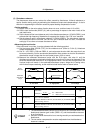
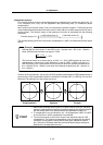
LMC compensation compensates the response
delay during reversal by adding the torque
command set with the parameters when the speed direction changes. There are two types of LMC
compensation.
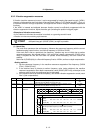
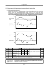
<Setting method>
<1> Set the special servo function selection 1 (SV027 (SSF1)) bit 9. (The LMC compensation type 2 will
start).
<2> Set the compensation amount with a stall % (rated current % for the general-purpose motor) unit in
the lost motion compensation 1 (SV016 (LMC1)). The LMC1 setting value will be used for
compensation in the positive and negative directions when SV041 (LMC2) is 0.
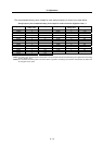
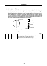
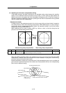
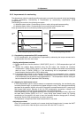
<3> If the compensation amount is to be changed in the direction to be compensated, set LMC2. The
compensation direction setting will be as shown below with the CW/CCW setting in the NC parameter.
If only one direction is to be compensated, set the side not to be compensated as -1.
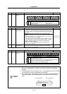
No. Abbrev. Parameter name Explanation Setting range
SV016 LMC1 Lost motion
compensation 1
Set the compensation value using the motor's stall current as a reference.
The standard setting value is double the friction torque. The compensation
amount will be 0 when "0" is set.
-1 to 200
(Stall current %)
SV041 LMC2 Lost motion
compensation 2
S
et this with SV016 (LMC1) only when you wish to set the lost motion
c
ompensation amount to be different depending on the command
d
irections.
Set to "0" as a standard.
-1 to 200
(Stall current %)
SV027 SSF1 Special servo
function selection 1 F EDCBA98765 4 3 2 10
zrn2 lmc vfct
bit
Meaning when "0" is set Meaning when "1" is set
8 Set the compensation amount with SV016 (LCM1) and SV041 (LCM2).
9
lmc
00: Lost motion compensation stop
10: Lost motion compensation type 2
01: Setting prohibited 11: Setting prohibited
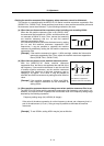
Compensation
point
CW CCW
A X axis: LMC2 X axis: LMC1
B Y axis: LMC1 Y axis: LMC2
C X axis: LMC1 X axis: LMC2
D Y axis: LMC2 Y axis: LMC1
+Y
-Y
+X
-X
A
The X axis command direc-
tion changes from + to -.
D
The Y axis command direc-
tion changes from + to -.
B
The Y axis command direc-
tion changes from - to +.
The X axis command direc-
tion changes from - to +.
C