


Workman HD SeriesPage 6 − 40Drive Train
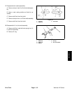
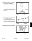
5. Assemble differential gears:
A. Apply moly disulfide grease on pinion liners,
holes of pinion gears, side gear liners and hubs of
side gears.
B. Install side gear liners, side gears, pinion liners
and pinion gears.
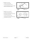
C. Rotate side gears until holes of pinion gears and
liners align with holes of differential case.
D. Insert pinion shaft. Grease the shaft to aid as-
sembly.
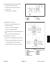
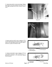
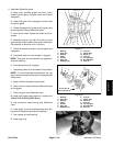
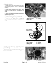
E. Assemble lock pin (Fig. 69). Drive the pin to the
approximate center location of the pinion mate shaft.
Pay attention to direction of slit in lock pin.
F. Check for smooth revolution of pinion gears and
side gears.
G. Completely clean oil from threads in ring gear.
NOTE: Ring gear and countershaft are supplied in
matched sets only.
H. Insert dowel pins onto ring gear.
I. Completely clean oil from threads of cap screws.
NOTE: It is recommended that whenever the ring
gear screws are removed that they be replaced with
new screws.
J. Apply Loctite to threads of cap screws.
K. Clean oil from contact surface of differential case
and ring gear.
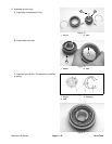
L. Drive ring gear onto differential case.
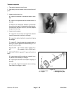
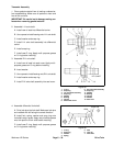
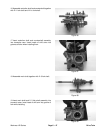
M. Install and tighten cap screws to a torque from
18.5 to 22 ft−lb (24.5 to 29.5 N−m).
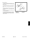
N. Use a press to install bearing onto differential
case.
O. Install slider. Put moly disulfide grease onto slid-
ing area of differential case before installing.
P. Use a press to install bearing.
Q. Install snap ring.
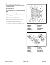
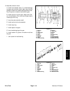
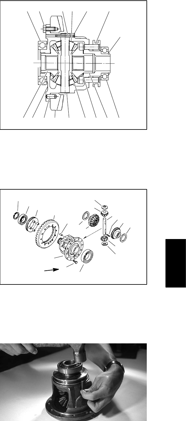
1. Bearing
2. Snap ring
3. Bearing
4. Slider
5. Screws
6. Ring gear
7. Dowel pin (2)
8. Lock pin
9. Pinion shaft
10. Pinion (2)
11. Liner (2)
12. L.H. side gear
13. R.H. Side gear
14. Liner (2)
Figure 67
1
15
5 SLIT 11 8 4
2
12 7 6 9 10 14 13 3
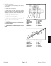
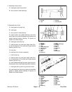
1. Bearing
2. Snap ring
3. Bearing
4. Slider
5. Screws
6. Ring gear
7. Dowel pin (2)
8. Lock pin
9. Pinion shaft
10. Pinion (2)
11. Liner (2)
12. L.H. side gear
13. R.H. Side gear
14. Liner (2)
2
3
4
6
7
11
10
14
13
9
8
12
14
10
11
1
5
15
Figure 68
18.5 to 22 ft−lb
(24.5 to 29.5 N−m)
Figure 69
Drive Train