


Workman HD SeriesPage 9 − 40Hydraulic System
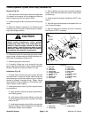
Primary Hydraulic System Gear Pump (Workman HD)
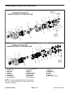
Removal (Fig. 29)
1. Park vehicle on a level surface, raise and support bed
(if installed), shut engine off and engage the parking
brake. Remove key from the ignition switch.
2. Loosen pump drive belt and remove belt from pump
pulley.
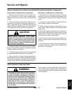
3. Read the General Precautions for Removing and
Installing Hydraulic System Components at the begin-
ning of this chapter section.
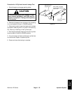
CAUTION
Before performing any service or repair on hy-
draulic system components, relieve system
pressure to avoid injury from pressurized hy-
draulic oil. Stop the engine, remove key from the
ignition switch, rotate the steering wheel in both
directions, lower the bed onto the bed support
and operate other hydraulic accessories.
4. Disconnect hydraulic hoses from gear pump. Install
caps or plugs in hoses and pump fittings to prevent con-
tamination and leakage of hydraulic oil.
5. Remove gear pump from mount.
6. If hydraulic fittings are to be removed from gear
pump, mark fitting orientation to allow correct assembly.
Remove fittings from pump and discard O−rings.
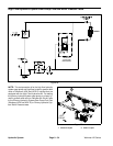
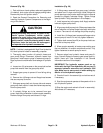
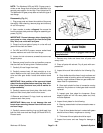
Installation (Fig. 29)
1. If fittings were removed from gear pump, lubricate
and place new O−rings onto fittings. Install fittings into
pump openings using marks made during the removal
process to properly orientate fittings. Tighten fittings
(see Hydraulic Fitting Installation in the General Infor-
mation section of this chapter).
2. Install gear pump to mount (Fig. 29) using the follow-
ing instructions:
A. Apply antiseize lubricant to gear pump shaft be-
fore installing pulley.
B. Install pump suction hose to fitting on pump, then
fill pump through pressure port of pump, with clean
Dexron III ATF.
C. Install pump pressure hose to fitting on pump (see
Hydraulic Hose and Tube Installation in the General
Information section of this chapter).
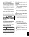
3. After installing the pump and connecting hydraulic
hoses, install belt and adjust belt tension (see Opera-
tor’s Manual).
4. Check oil level in transaxle. Add Dexron III ATF if nec-
essary.
5. Start the engine and operate at idle speed until air is
out of hydraulic system.
6. Stop the engine and recheck oil level in transaxle.
Add Dexron III ATF if necessary.
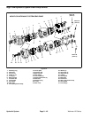
9
6
7
8
1
10
11
3
5
2
12
4
15
16
13
17
14
18
ANTISIEZE
LUBRICANT
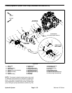
1. Drive belt
2. Lock nut
3. Flat washer
4. Pump pulley
5. Flange head screw
6. Carriage screw
7. Mount
8. Suction hose
9. Square key
10. Gear pump
11. Lock nut (2)
12. Pressure hose
13. Hose clamp
14. O−ring
15. Hydraulic fitting
16. O−ring
17. Hydraulic fitting
18. O−ring
Figure 29
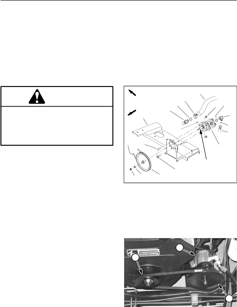
FRONT
RIGHT
1. Gear pump
2. Pump pulley
3. Engine pulley
Figure 30
2
1
3