


Workman HD Series Page 9 − 25 Hydraulic System
Procedure for Primary Hydraulic System Gear Pump
Flow Test (Workman HD)
The primary hydraulic system gear pump is designed to
satisfy both steering cylinder and lift cylinder needs sim-
ultaneously (at full speed throttle). If unit steering is slug-
gish or otherwise performs poorly, see Steering Control
Valve and Steering Cylinder Test in this chapter.
If lift operation is unsatisfactory, check lift control valve
and/or lift cylinders. Additional information on these
components is available in this chapter.
If both steering and lift operations perform poorly, per-
form the primary hydraulic system gear pump flow test
and relief valve pressure test. This test compares fluid
flow at No Load with fluid flow Under Load. A drop in flow
under load of more than 15% indicates the gears and
wear plates in the pump have worn. Continued operation
with a worn pump can generate excessive heat and
cause damage to the seals and other components in the
hydraulic system.
Special Equipment Required:
S Flow Meter with Pressure Gauge that has at least
a 5 GPM (19 LPM) capacity.
1. Park vehicle on a level surface, raise and support bed
(if installed), shut engine off and engage the parking
brake. After turning engine off, operate all hydraulic con-
trols to relieve hydraulic system pressure.
2. Make sure that gear pump drive belt is adjusted prop-
erly (see Operator’s Manual).
CAUTION
Prevent personal injury and/or damage to equip-
ment. Read all WARNINGS, CAUTIONS and Pre-
cautions for Hydraulic Testing at the beginning
of this section.
IMPORTANT: Make sure that the oil flow indicator
arrow on the flow meter is showing that the oil will
flow from the pump, through the tester and into the
hydraulic hose.
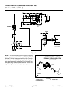
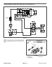
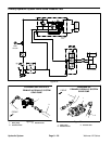
3. With the engine off, clean hose fitting and disconnect
the pressure hose from the gear pump (Fig. 19). Install
tester with pressure gauges and flow meter in series be-
tween the gear pump and the disconnected hose. Make
sure the tester flow control valve is open.
4. Make sure the hydraulic reservoir (transaxle) is full
after connecting the tester.
CAUTION
The engine must be running to perform hydraulic
tests. To guard against possible personal injury,
engage parking brake and keep clothing, hands,
feet, face and other parts of the body away from
moving vehicle parts while testing.
5. Make sure hydraulic oil is at normal operating tem-
perature by operating the vehicle for approximately ten
(10) minutes. Check for hydraulic leakage and correct
before proceeding with test.
6. Fully depress and hold accelerator pedal. Check that
engine speed is 3600 RPM and also check that pump
speed is approximately 2270 RPM. Verify engine and
pump speed with a phototac.
7. Verify pump flow at No Load as follows:
A. Record tester pressure and flow readings at no
load. Unrestricted pump output should be approxi-
mately 3.5 GPM (13.2 LPM).
8. Verify pump flow Under Load as follows:
CAUTION
Do not close tester valve fully when perform-
ing this test. In this test, the hydraulic tester is
positioned before the circuit relief valve. Pump
damage can occur if the fluid flow is fully re-
stricted by fully closing the tester flow control
valve.
A. Watch pressure gauge carefully while slowly clos-
ing the flow control valve until 1500 PSI (103 Bar) is
obtained on gauge.
B. Record tester pressure and flow readings under
load.
9. Release accelerator pedal and shut off engine.
Hydraulic
System