


Workman HD Series Page 9 − 43 Hydraulic System
NOTE: The Workman HDX and HDX−D gear pump in-
cludes a rear flange that will allow the installation of a
second pump section for the High Flow Hydraulics Kit.
The Workman HD gear pump does not have this type of
rear flange.
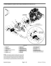
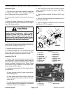
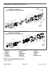
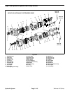
Disassembly (Fig. 31)
1. Plug pump ports and clean the outside of the pump
thoroughly. After cleaning, remove plugs and drain any
oil out of the pump.
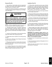
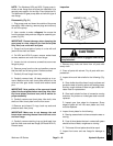
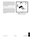
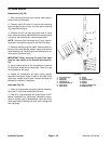
2. Use a marker to make a diagonal line across the
front thrust plate, body and rear flange for assembly pur-
poses (Fig. 32).
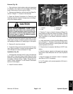
IMPORTANT: Prevent damage when clamping the
gear pump in a vise; clamp on the front thrust plate
only. Also, use a vise with soft jaws.
3. Clamp front thrust plate of pump in a vise with soft
jaws with the shaft end down.
4. On HDX and HDX−D pumps, remove socket head
screws, washers and cover from rear flange.
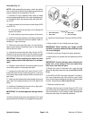
5. Loosen, but do not remove, screws that secure rear
flange to pump.
6. Remove pump from the vise and position pump so
that the shaft end is facing down. Remove screws.
7. Carefully lift rear flange from body.
8. Carefully remove body. Lift body straight up to re-
move. Make sure the rear thrust plate remains on the
drive and idler gear shafts. Locate and retrieve dowel
pins.
IMPORTANT: Note position of the open and closed
side of the thrust plates before removing. Also, iden-
tify thrust plates (front and rear) with a marker for
proper assembly.
9. Carefully remove rear thrust plate, idler shaft, drive
shaft and front thrust plate from the front cover.
10.Remove and discard O−rings, back−up seals and
pressure seals from pump.
IMPORTANT: Make sure to not damage the seal
bores when removing the seal from the front cover
and rear flange.
11. Carefully remove retaining ring and shaft seal from
both the front cover and rear flange (HDX and HDX−D).
Discard seals.
Inspection
Figure 32
MARKER LINE
CAUTION
Use eye protection such as goggles when using
compressed air.
1. Remove any nicks and burrs from all parts with
emery cloth.
2. Clean all parts with solvent. Dry all parts with com-
pressed air.
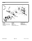
3. Inspect drive and idler shafts for the following (Fig.
33):
A. Gear shafts should be free of rough surfaces and
excessive wear at bushing points and sealing areas.
Scoring, rough surfaces or wear on gear shafts indi-
cates need for replacement.
B. Gear teeth should be free of excessive scoring
and wear. Any broken or nicked gear teeth must be
replaced.
C. Inspect gear face edge for sharpness. Sharp
edges of gears will mill into wear plates and, thus,
must be replaced.
4. Inspect thrust plates for the following:
A. Bearing areas should not have excessive wear or
scoring.
B. Face of thrust plates that are in contact with gears
should be free of wear, roughness or scoring.
C. Thickness of thrust plates should be equal.
5. Inspect front cover and rear flange for damage or
wear.
Hydraulic
System