


Workman HD SeriesPage 8 − 26Electrical System
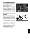
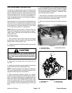
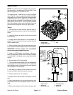
Electric Fan Thermal Switch (Workman HDX−D)
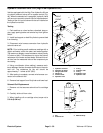
The thermal fan switch is threaded into the thermostat
housing on the engine (Fig. 37). The fan switch is a nor-
mally open switch that closes when the engine coolant
temperature reaches 190F to 210F (88C to 99C). There
is a green wire attached to the switch. When the thermal
fan switch closes, the radiator fan is energized.
Testing
1. Park machine on a level surface, raise bed, stop en-
gine, apply parking brake and remove key from ignition
switch.
2. Install bed support on bed lift cylinder to prevent bed
from lowering.
CAUTION
Make sure engine is cool before removing the
thermal fan switch.
3. Lower the coolant level in the engine, remove wire
harness connector from thermal fan switch and remove
the switch from the engine.
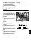
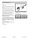
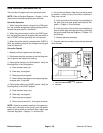
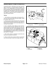
4. Put fan switch in a container of oil with a thermometer
and slowly heat the oil (Fig. 38).
CAUTION
Handle the hot oil with extreme care to prevent
personal injury or fire.
NOTE: Prior to taking resistance readings with a digital
multimeter, short the meter test leads together. The me-
ter will display a small resistance value (usually 0.5
ohms or less). This resistance is due to the internal resis-
tance of the meter and test leads. Subtract this value
from from the measured value of the component you are
testing.
5. Check continuity of the switch with a multimeter
(ohms setting). The thermal fan switch is normally open
and should close at approximately 190F to 210F (88C to
99C). As the switch cools, it should open at approximate-
ly the same temperature.
6. Replace thermal fan switch if necessary.
7. Install fan switch to the water pump.
A. Clean threads of water pump housing and switch
thoroughly. Apply thread sealant to the threads of the
switch.
B. Install switch into the water pump housing and
tighten.
C. Connect green wire harness wire to switch.
8. Fill engine cooling system.
9. Remove bed support from lift cylinder and lower bed.
1. Thermostat housing
2. Thermal fan switch
3. Temp sender
Figure 37
3
1
2
Figure 38