


Workman HDXPage 3 − 18Kubota EFI Gasoline Engine
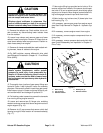
CAUTION
Do not open radiator cap or drain coolant if the
radiator or engine is hot. Pressurized, hot cool-
ant can escape and cause burns.
Ethylene−glycol antifreeze is poisonous. Dis-
pose of coolant properly or store it in a properly
labeled container away from children and pets.
9. Remove the radiator cap. Drain radiator into a suit-
able container by disconnecting lower radiator hose
from the radiator.
10.Loosen hose clamps and remove upper and lower
radiator hoses from engine. Remove R−clamp that se-
cures lower radiator hose to engine mount. Position ra-
diator hoses away from engine.
11. Remove all clamps and cable ties used to attach wir-
ing harness, hoses or cables to the engine.
12.On 4WD vehicles, remove differential drive shaft
(see Differential Driveshaft in Chapter 10 − Front Wheel
Drive (4WD)).
CAUTION
Before performing any service or repair on hy-
draulic system components, relieve system
pressure to avoid injury from pressurized hy-
draulic oil. Rotate the steering wheel in both di-
rections, make sure that the bed is lowered onto
the bed support and operate any other hydraulic
accessories.
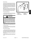
13.Thoroughly clean junction of gear pump fittings and
hydraulic hoses. Label hydraulic hoses for assembly
purposes. Disconnect hydraulic hoses from gear pump.
Install caps or plugs in hoses and pump fittings to pre-
vent contamination and leakage of hydraulic oil.
14.Put blocking under transaxle to prevent the transaxle
from moving during engine removal.
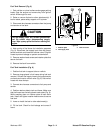
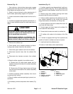
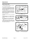
15.Loosen and remove two (2) flange nuts, snubbing
washers and cap screws that secure engine mounts to
engine support (Fig. 16).
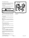
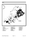
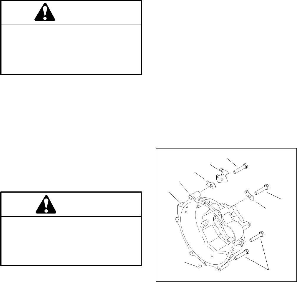
16.Remove six (6) cap screws that secure clutch bell
housing to engine. Note location of harness bracket(s)
(Fig. 17).
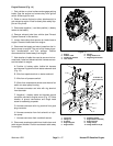
17.Use engine lifting lugs provided and a hoist or lift to
remove engine from chassis. One person should oper-
ate hoist or lift and a second person should help guide
engine out of chassis. Move engine forward before lift-
ing to disengage transaxle input shaft from clutch.
18.Note location and retrieve two (2) dowel pins from
bell housing (Fig. 17).
19.If necessary, remove gear pump from engine mount
(see Gear Pump Removal in Chapter 9 − Hydraulic Sys-
tem).
20.If necessary, remove engine mount from engine.
21.If necessary, remove coupler components from en-
gine pulley.
22.If necessary, remove pressure plate and clutch disc
(see Clutch Disassembly and Inspection in Chapter 6 −
Drive Train).
Figure 17
1. Bell housing
2. Cap screw (6)
3. Harness bracket
4. Dowel pins (2)
5. Harness bracket
2
3
4
1
2
2
3
4
5