


Workman HDX Page 3 − 19 Kubota EFI Gasoline Engine
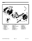
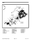
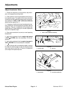
Engine Installation (Fig. 14)
1. Install pressure plate and clutch disc if removed (see
Installing Clutch Disc and Cover in Chapter 6 − Drive
Train).
2. If coupler assembly was removed, assemble coupler
to engine pulley. Apply Loctite #242 (or equivalent) to
threads of flange head screws that secure coupler to en-
gine pulley. Torque fasteners to 15 to 20 ft−lb (20 to 27
N−m).
3. If engine mount was removed, secure mount to en-
gine with seven (7) flange head screws. Do not install
the screw used to secure the ground connections to the
engine at this time.
4. If gear pump was removed, install gear pump to en-
gine mount (see Gear Pump Installation in Chapter 9 −
Hydraulic System in this manual).
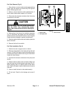
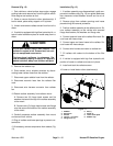
5. Install two (2) dowel pins in bell housing bores (Fig.
14).
6. Make sure that snubbing washer is positioned on top
of both engine mounts (Fig. 13).
7. Apply anti−seize lubricant to splines on transaxle in-
put shaft.
8. Use engine lifting lugs provided and a hoist or lift to
install engine to chassis. One person should operate
hoist and second person should help guide engine to
machine. Align splines on transaxle input shaft and
clutch while moving engine to bell housing on transaxle.
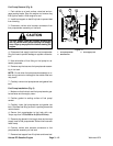
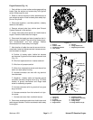
9. Secure bell housing to engine with six (6) cap screws
and harness bracket(s) (Fig. 17).
10.Secure engine mount to engine support with two (2)
cap screws, snubbing washers and flange nuts (Fig.
16).
11. Remove plugs from hydraulic hoses and gear pump
fittings. Connect hydraulic hoses to gear pump (see Hy-
draulic Hose and Tube Installation in Chapter 9 − Hy-
draulic System).
12.On 4WD vehicles, install differential drive shaft (see
Differential Driveshaft Installation in Chapter 10 − Front
Wheel Drive (4WD)).
13.Install upper and lower radiator hoses to engine and
secure with hose clamps. Install R−clamp to secure low-
er radiator hose to engine mount.
14.Fill radiator with coolant (see vehicle Operator’s
Manual).
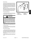
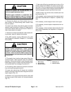
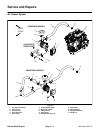
15.Connect wire harness connectors to engine compo-
nents. Secure wire harness to machine with cable ties
in locations noted during engine removal.
A. Positive (+) battery cable, fusible link harness
and harness ring terminal from starter solenoid stud
(Fig. 12).
B. Wire from spade terminal on starter solenoid.
C. Wire from oil pressure switch.
D. Wires from temperature sender and thermal fan
switch on water pump housing.
E. Harness connector and wire with ring terminal
from alternator.
F. Negative (−) battery cable and harness ground
connector secured to engine mount (Fig. 15). Note
location of ground connections and flange head
screw for assembly purposes.
G. Harness connector with ring terminal from glow
plug connector.
H. Harness connector from fuel solenoid on injec-
tion pump.
I. Harness connector from crankshaft sensor.
16.Secure accelerator cable to throttle lever on engine
and cable support bracket.
17.Install air intake hose to engine and secure with hose
clamp.
18.Connect fuel supply and return hoses to fuel injection
pump on engine. Secure hoses with hose clamps.
19.Install exhaust tube to vehicle (see Exhaust System
Installation in this section).
20.Connect positive (+) and then negative (−) battery
cables to the battery.
21.Check operation and adjustment of accelerator ped-
al (see Adjust Accelerator Cable in this chapter).
Kubuta EFI
Gasoline Engine