


Workman HD Series Page 7 − 29 Chassis
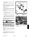
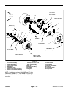
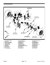
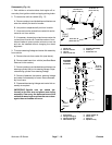
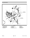
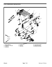
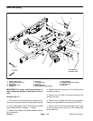
Removal (Fig. 19)
WARNING
FRONT SUSPENSION IS SPRING LOADED! To
prevent possible personal injury, use special
tool to remove compression springs before dis-
assembling the front suspension.
1. Park vehicle on a level surface, shut engine off, re-
move key from ignition switch and apply parking brake.
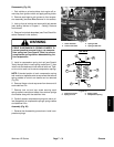
2. If servicing upper control arm, remove front com-
pression springs (see Front Compression Spring Ser-
vice in this section).
NOTE: Front compression springs do not need to be re-
moved if servicing only the lower control arm.
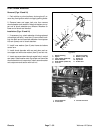
3. Remove cap screw and flange nut that secure af-
fected control arm ball joint to knuckle. Separate ball
joint from knuckle. Inspect ball joint seal and replace if
damaged.
4. Remove control arm from vehicle frame.
5. Disassemble control arm as needed.
A. Remove retaining ring and press ball joint out of
control arm.
B. Press flange bushings from control arm.
Installation (Fig. 19)
1. Assemble control arm.
A. Press ball joint into control arm and secure with
retaining ring. Make sure that grease fitting is in ball
joint.
B. Lightly oil flange bushings and press bushings
fully into control arm.
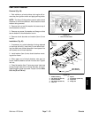
2. Install ball joint seal over shaft on ball joint. Edge of
seal must be inserted into ball joint slot.
3. Install and secure control arm to vehicle with re-
moved fasteners. Tighten lock nuts from 70 to 80 ft−lb
(94 to 109 N−m).
4. Align recess in ball joint stud with hole in knuckle.
Slide ball joint stud into knuckle and secure with cap
screw and flange nut. Torque nut from 40 to 50 ft−lb (55
to 67 N−m).
5. If removed, install front compression springs (see
Front Compression Spring Service in this section).
6. Grease ball joint.
Chassis