


Workman HDX−D
Page 4 − 11
Kubota Diesel Engine
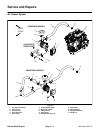
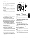
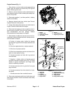
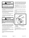
Fuel Tank Removal (Fig. 7)
1. Park vehicle on a level surface and engage parking
brake. Stop the engine and remove key from ignition
switch. Allow engine to cool.
2. Raise or remove the bed or other attachment(s). If
bed is raised, place safety support on lift cylinder.
3. Disconnect wire harness connector from fuel sender
on fuel tank.
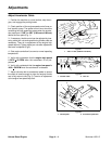
4. Note routing of fuel hoses for installation purposes
(Fig. 8). Disconnect fuel hoses from fuel sender and rol-
lover valve. Plug fuel hoses to prevent leakage or fuel
contamination.
5. Remove washer head screws and retainer plate that
secure fuel tank.
6. Remove fuel tank from vehicle.
Fuel Tank Installation (Fig. 7)
1. Position fuel tank to support tube.
2. Remove plugs placed in fuel hoses during fuel tank
removal. Connect fuel hoses to fuel sender and rollover
valve. Secure fuel hoses with hose clamps.
3. Connect wire harness connector to fuel sender.
4. Position retainer plate to tank and frame. Make sure
that fuel hoses are correctly routed under retainer plate.
Secure the fuel tank by pressing down on retainer plate
while installing and tightening washer head screws.
5. Lower or install the bed or other attachment(s).
6. Fill fuel tank. Check for fuel leakage and correct if
found.
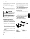
Fuel Sender Removal (Fig. 7)
1. Park vehicle on a level surface, raise bed and en-
gage parking brake. Stop the engine and remove key
from ignition switch. Allow engine to cool.
2. Install bed support on bed lift cylinder to prevent bed
from lowering.
3. Disconnect vehicle wire harness connectors from
fuel sender assembly on fuel tank.
4. Disconnect fuel hoses from fuel sender. Plug fuel
hoses to prevent leakage or system contamination.
5. Note orientation of fuel fittings on fuel sender for as-
sembly purposes.
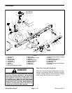
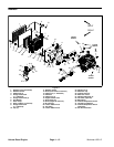
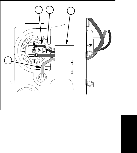
Figure 8
1. Retainer plate
2. Fuel supply hose
3. Fuel return hose
4. Tank vent hose
1
3
4
2
6. Remove cap that secures fuel sender assembly in
fuel tank.
NOTE: Do not allow fuel sender assembly to rotate dur-
ing removal or damage to the sender float arm may res-
ult.
7. Carefully remove fuel sender and gasket from tank.
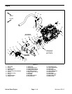
Fuel Sender Installation (Fig. 7)
1. Make sure that fuel tank and fuel sender gasket sur-
faces are thoroughly clean.
2. Position gasket to sealing surface of fuel sender.
3. Carefully insert fuel sender and gasket into tank.
Orientate fuel fittings so that it is pointing toward the ve-
hicle frame.
4. Secure fuel sender to fuel tank with cap. Torque cap
from 175 to 200 in−lb (20 to 22 N−m).
5. Remove plugs placed in fuel hoses and connect
hoses to fuel sender. Secure fuel hoses with hose
clamps.
6. Connect vehicle wire harness connectors to fuel
sender assembly on fuel tank.
7. Remove bed support from lift cylinder and lower bed.
Kubota
Diesel Engine