


Workman HD Series Page 8 − 17 Electrical System
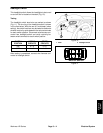
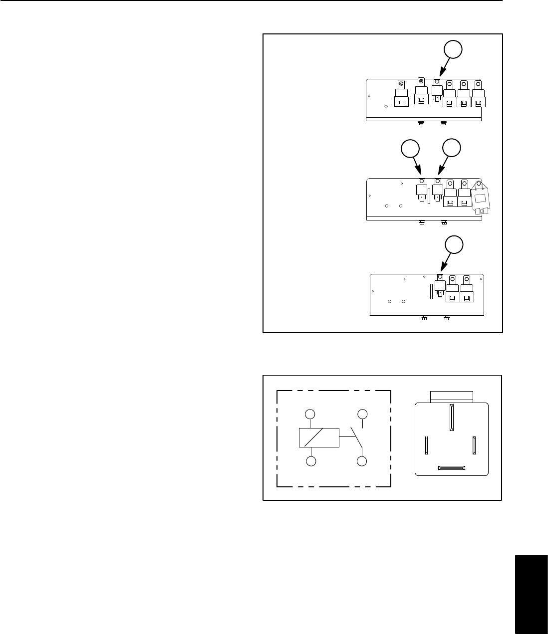
Power Relay (Four Terminals)
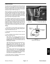
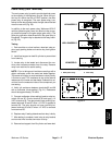
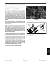
The main power relay is used to provide electrical power
to the majority of the Workman circuits. When the igni-
tion key is in either the ON or START position, the main
power relay is energized. The main power relay is at-
tached to the relay bracket under the right side of the bed
near the rear axle (Fig. 20).
In addition to the main power relay, Workman HDX−D
vehicles (diesel engine) use a four terminal relay to sup-
ply electrical power to the glow plugs (glow relay). The
glow plug controller determines when the glow relay is
energized. The glow relay is attached to the relay brack-
et (Fig. 20).
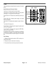
Testing
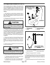
1. Park machine on a level surface, raise bed, stop en-
gine, apply parking brake and remove key from ignition
switch.
2. Install bed support on bed lift cylinder to prevent bed
from lowering.
3. Locate relay to be tested and disconnect the ma-
chine wire harness connector from the relay. Remove
relay from machine for easier testing.
NOTE: Prior to taking small resistance readings with a
digital multimeter, short the meter test leads together.
The meter will display a small resistance value (usually
0.5 ohms or less). This resistance is due to the internal
resistance of the meter and test leads. Subtract this val-
ue from from the measured value of the component you
are testing.
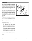
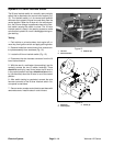
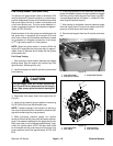
4. Verify coil resistance between terminals 85 and 86
with a multimeter (ohms setting) (Fig. 21). Resistance
should be approximately 72 ohms.
5. Connect multimeter (ohms setting) leads to relay ter-
minals 30 and 87. Ground terminal 86 and apply +12
VDC to terminal 85. The relay should have continuity be-
tween terminals 30 and 87 when +12 VDC is applied to
terminal 85. The relay should not have continuity be-
tween terminals 30 and 87 when +12 VDC is removed
from terminal 85.
6. Replace relay if testing determines that relay is faulty.
7. After testing is complete, install relay to relay bracket
and connect wire harness connector to relay.
8. Remove bed support from lift cylinder and lower bed.
HDX MODELS
HDX−D MODELS
1
2
1
1. Main power relay 2. Glow relay
Figure 20
HD MODELS
1
Figure 21
86 87
85 30
85 86
87
30
Electrical
System