


Workman HD Series Page 8 − 27 Electrical System
Speed Sensor
NOTE: The speed sensor and speedometer are stand-
ard equipment on the Workman HDX and HDX−D, and
optional equipment on the Workman HD.
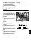
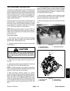
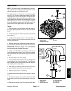
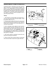
The speed sensor is attached to the upper transaxle
cover (Fig. 39). It uses a magnetically based, Hall Effect
integrated circuit to provide a signal to the speedometer.
As the differential in the transaxle turns, the sensor accu-
rately senses the movement of the differential ring gear
teeth passing by the sensor. The red striped connector
wire is the sensor positive lead, the black wire is the
ground lead and the green wire is the signal output.
Testing
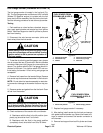
1. Park machine on a level surface, raise bed, stop en-
gine, apply parking brake and remove key from ignition
switch.
2. Install bed support on bed lift cylinder to prevent bed
from lowering.
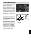
3. Locate traction speed sensor on the transaxle as-
sembly. Disconnect the wire harness connector from the
traction speed sensor.
4. Remove flange head screw that secures speed sen-
sor to transaxle. Remove speed sensor from transaxle.
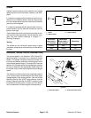
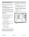
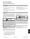
IMPORTANT: Incorrect jumper wire connections
during testing can damage the sensor.
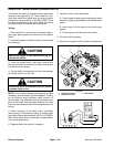
5. Using a +12 VDC battery, a multimeter, a 1K ohm re-
sistor and appropriate jumper wires, connect the battery
and multimeter to the speed sensor using Figure 40 as
a guide.
6. Set multimeter to DC volts setting.
7. The multimeter should display very low voltage when
a metal object is held near the sensor tip. The multimeter
should display battery voltage when the metal object is
moved away from the sensor tip.
8. After testing is complete, remove jumper wires, resis-
tor and multimeter leads from sensor connector.
9. Replace speed sensor if necessary.
10.Inspect sensor seal condition and replace if neces-
sary.
11. Install speed sensor into transaxle and secure with
flange head screw. Reconnect speed sensor to wire har-
ness.
12.Remove bed support from lift cylinder and lower bed.
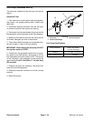
1. Speed sensor
2. Flange head screw
3. Seal
Figure 39
1
2
3
1. Speed sensor
2. Sensor tip
3. Sensor connector
4. Red striped wire
5. Green wire
6. Black wire
Figure 40
BAC
−
+
12 VDC
6
4
2
3
1
5
1K ohm
resistor
Electrical
System