


Workman HDX/HDX−DPage 10 − 4Front Wheel Drive (4WD)
Service and Repairs
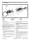
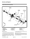
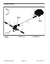
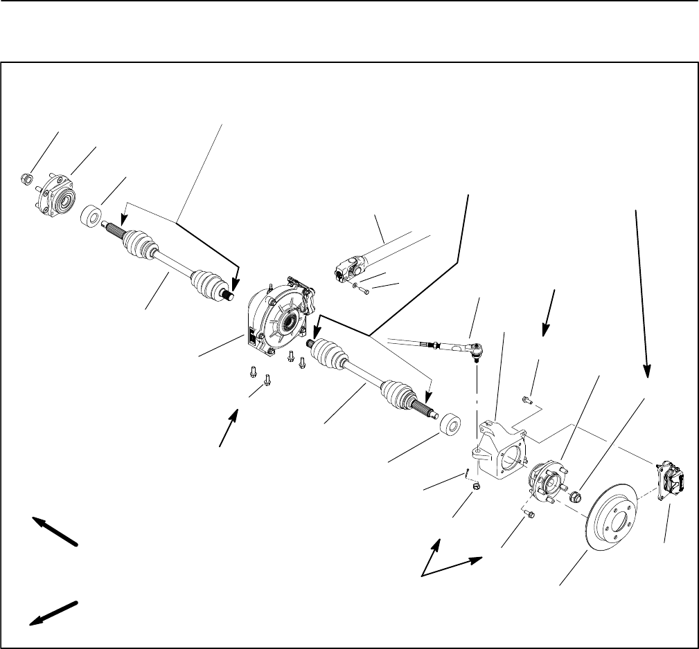
Constant Velocity (CV) Axle Assembly
1. Spindle nut
2. CV axle assembly
3. Differential assembly
4. Flange head screw (4)
5. Driveshaft
6. Cap screw
7. Flat washer
8. Wheel hub assembly
9. Tie rod assembly
10. Axle spacer
11. Flange head screw
12. Brake caliper (LH shown)
13. Brake rotor
14. Slotted hex nut
15. Cotter pin
16. Knuckle (LH shown)
Figure 1
FRONT
RIGHT
1
2
3
4
5
6
7
8
9
10
11
12
13
14
15
35 to 40 ft−lb
(48 to 55 N−m)
35 to 40 ft−lb
(48 to 55 N−m)
170 to 180 ft−lb
(231 to 244 N−m)
ANTISEIZE
LUBRICANT
ANTISEIZE
LUBRICANT
1
2
10
8
11
16
STAKED
20 to 26 ft−lb
(27 to 35 N−m)
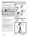
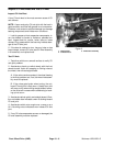
Disassembly (Fig. 1)
1. Park vehicle on a level surface, shut engine off, re-
move key from ignition switch and apply parking brake.
2. For Constant velocity (CV) axle to be removed, re-
move wheel assembly, brake caliper and brake rotor
(see Brake System Disassembly in Chapter 7 − Chassis
in this manual).
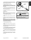
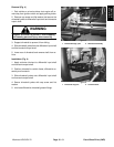
3. Remove spindle nut from the threaded shaft of the
CV axle. Discard spindle nut.
NOTE: Spindle nuts are staked (deformed) to the CV
axle during assembly. Clear away the deformed area of
the nut before removing the nut from the axle or damage
to the axle threads will occur.