


Workman HD Series Page 6 - 13 Drive Train
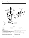
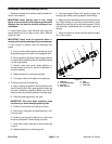
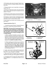
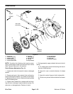
Removal (Fig. 7)
1. Park vehicle on a level surface, shut engine off and
remove key from ignition switch.
2. For driveshaft to be serviced, remove wheel, brake
caliper, brake rotor and wheel hub (see Wheel Hub Re-
moval in Chapter 7 - Chassis in this manual).
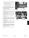
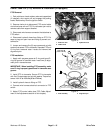
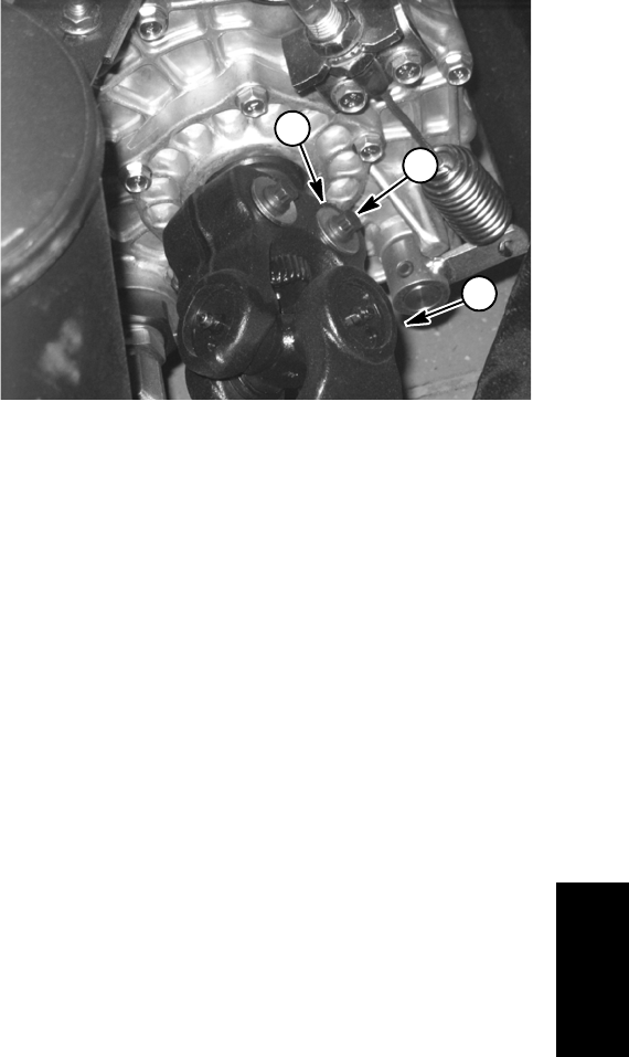
3. Loosen and remove flange nuts, cap screws and
hardened washers that secure driveshaft to transaxle
shaft (Fig. 8).
4. Slide driveshaft from transaxle shaft and remove
from vehicle.
5. If necessary, loosen and remove flange nut that se-
cures splined shaft to driveshaft. Remove splined shaft
from driveshaft.
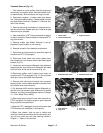
NOTE: Spindle nuts are staked (deformed) to the
splined shaft during assembly. Clear away the deformed
area of the nut before removing the nut from the s haft or
damage to the shaft threads will occur.
Installation (Fig. 7)
1. If removed, attach splined shaft to driveshaft:
A. Apply antiseize lubricant to splined shaft and
install into driveshaft.
B. Apply Loctite #271 (or equivalent) to threads of
splined shaft.
C. Install new flange nut onto splined shaft and tight-
en. Torque spindle nut from 170to180ft-lb(231to
244 N- m).
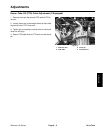
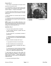
2. Secure driveshaft to transaxle shaft (Fig. 8):
A. Apply antiseize lubricant to transaxle shaft.
B. Slide driveshaft yoke onto transaxle shaft.
C. Align mounting holes in driveshaft with relief in
transaxle shaft.
D. Install cap screws, hardened washers and flange
nuts to secure driveshaft to transaxle shaft. Torque
fasteners from 40 to 45 ft- lb (55 to 61 N- m).
3. Install wheel hub, brake rotor, brake caliper and
wheel (see Wheel Hub Installation in the Service and
Repairs section of Chapter 7 - Chassis). Make sure that
wheel lug nuts are properly torqued from 80 to 90 ft- lb
(109 to 122 N- m).
4. Lubricate driveshaft grease fittings.
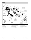
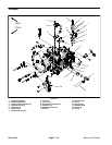
1. Driveshaft
2. Cap screw
3. Hardened washer
Figure 8
1
2
3
Drive Train