


Workman HD SeriesPage 8 − 8Electrical System
Component Testing
This section will define electrical component operation
and supply test procedures that can be performed on
those components.
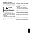
For accurate resistance and/or continuity checks, elec-
trically disconnect the component being tested from the
circuit (e.g. unplug the clutch switch connector before
doing a continuity check on the switch).
NOTE: Electrical troubleshooting of any 12 volt power
connection can also be performed through voltage drop
tests without disconnecting the component.
CAUTION
When testing electrical components for continu-
ity with a digital multimeter, make sure that pow-
er to the circuit has been disconnected.
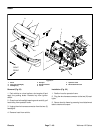
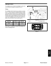
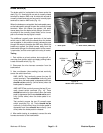
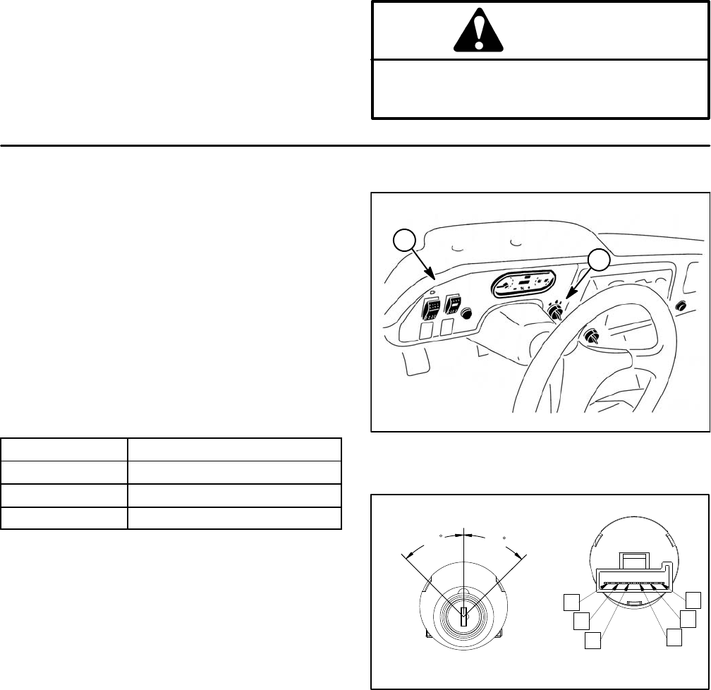
Ignition (Key) Switch
The ignition (key) switch has three positions (OFF, ON
and START). The ignition switch is located on the dash
(Fig. 6).
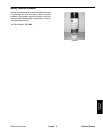
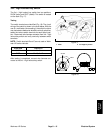
Testing
The switch terminals are identified as shown (Fig. 7).
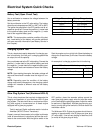
The circuit wiring of the ignition switch is shown in the
chart below. With the use of a multimeter (ohms setting),
the switch functions may be tested to determine whether
continuity exists between the various switch terminals
for each switch position. Disconnect wire harness con-
nector from key switch and verify continuity between
switch terminals.
POSITION
CIRCUITS
OFF NONE
ON B + C + F, D + E
START A + B + C
After testing is completed, connect wire harness con-
nector to ignition switch.
1. Dash 2. Ignition switch
Figure 6
1
2
Figure 7
REAR VIEW
FRONT VIEW
A
B
C
D
E
F
START
OFF
ON
45
45