


Workman HD Series Page 9 − 35 Hydraulic System
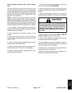
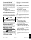
Procedure for High Flow Hydraulics System Gear
Pump Flow and Relief Pressure Tests
If both steering and lift operations perform poorly, per-
form the primary hydraulic system gear pump flow test
and relief valve pressure test. This test compares fluid
flow at No Load with fluid flow Under Load. A drop in flow
under load of more than 15% indicates the gears and
wear plates in the pump have worn. Continued operation
with a worn pump can generate excessive heat and
cause damage to the seals and other components in the
hydraulic system.
Special Equipment Required:
S Flow Meter with Pressure Gauge that has at least
a 10 GPM (38 LPM) capacity.
1. Make sure hydraulic oil is at normal operating tem-
perature by operating the vehicle for approximately ten
(10) minutes.
2. Park vehicle on a level surface, raise and support bed
(if installed), shut engine off and apply the parking brake.
After turning engine off, operate all hydraulic controls to
relieve hydraulic system pressure.
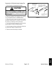
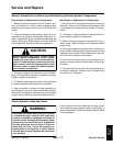
CAUTION
Prevent personal injury and/or damage to equip-
ment. Read all WARNINGS, CAUTIONS and Pre-
cautions for Hydraulic Testing at the beginning
of this section.
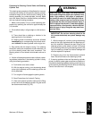
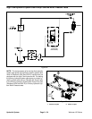
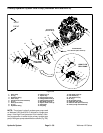
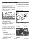
IMPORTANT: Make sure that the oil flow indicator
arrow on the flow meter is showing that the oil will
flow from the pressure coupler, through the tester
and into the return (tank) coupler (Fig. 27).
3. With the engine off, install tester with pressure
gauges and flow meter in series between the quick dis-
connect couplings at the rear of the vehicle. Make sure
the tester flow control valve is open.
4. Make sure the High Flow Kit reservoir is full.
CAUTION
The engine must be running to perform hydraulic
tests. To guard against possible personal injury,
engage parking brake and keep clothing, hands,
feet, face and other parts of the body away from
moving vehicle parts while testing.
5. After installing tester, start engine and run at idle
speed. Turn High Flow Kit switch ON and check for hy-
draulic leakage from connections. Correct before pro-
ceeding with test.
6. Depress accelerator pedal fully so engine or pump
speed is 3600 RPM. Verify engine or pump speed with
a phototac.
A. Record tester pressure and flow readings at no
load. Unrestricted pump output should be approxi-
mately 7.7 GPM (29 LPM).
7. Verify pump flow Under Load as follows:
A. Watch pressure gauge carefully while slowly clos-
ing the flow control valve until 1500 PSI (103 Bar) is
obtained on gauge.
B. Record tester pressure and flow readings under
load.
8. Open tester flow control valve, release accelerator
pedal to allow engine to return to low idle, turn High Flow
Kit switch OFF and stop engine.
9. The under load test flow reading (step 7.B) should not
drop more than 15% when compared to the no load test
flow reading (step 6.A). A difference in flow of more than
15%, or the inability to achieve specified pressure may
indicate:
A. Worn or stuck relief valve (SVRV)
B. A restriction in the pump intake line
C. The high flow hydraulic system gear pump is worn
and should be repaired or replaced
10.To test high flow hydraulic system relief pressure:
A. Make sure flow control valve on tester is fully
open.
B. Start engine and depress accelerator pedal so
engine or pump is operating at high idle (3600 RPM).
Turn High Flow Kit switch ON.
IMPORTANT: Close flow control valve on tester
only enough to get a system relief pressure read-
ing.
C. Watch pressure gauge carefully while slowly clos-
ing the tester flow control valve until the relief valve
opens.
Hydraulic
System