


Workman HD Series Page 9 − 53 Hydraulic System
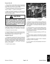
CAUTION
Before performing any service or repair on hy-
draulic system components, relieve system
pressure to avoid injury from pressurized hy-
draulic oil. Stop the engine, remove key from the
ignition switch, rotate the steering wheel in both
directions, lower or support the bed and operate
other hydraulic accessories.
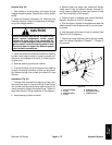
5. Remove hood to gain access to steering control (see
Hood Removal in Chapter 7 − Chassis in this manual).
6. Remove four (4) cap screws that secure steering
control valve to vehicle frame. Move steering valve (with
hydraulic hoses attached) away from vehicle frame.
7. Label and disconnect hydraulic hoses from steering
control valve (Fig. 40 and 41). Install caps or plugs in
hoses and valve fittings to prevent contamination and
leakage of hydraulic oil.
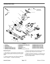
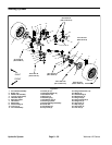
Installation (Fig. 39)
1. Replace O−rings on hydraulic fittings. Remove caps
and plugs from hoses. Connect hydraulic hoses to cor-
rect steering control valve ports (Fig. 40 and 41) (see Hy-
draulic Hose and Tube Installation in this chapter). Make
sure that hoses are not twisted while tightening.
2. Position steering control valve to vehicle frame with
port R toward front of vehicle (Fig. 40). Secure steering
control valve to vehicle with four (4) cap screws.
3. Install hydraulic hose cover over hoses and secure
with cable ties.
4. Install hood to frame (see Hood Installation in
Chapter 7 − Chassis in this manual).
5. Install steering wheel (see Steering Wheel Installa-
tion in Chapter 7 − Chassis in this manual).
6. Check oil level in transaxle (see vehicle Operator’s
Manual). Add Dexron III ATF if necessary.
7. Start the engine, operate at idle speed and rotate the
steering wheel in both directions until air is out of hydrau-
lic system.
8. Stop the engine and check oil level in transaxle. Add
Dexron III ATF if necessary.
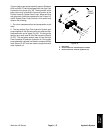
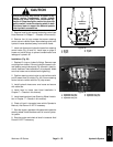
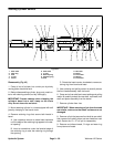
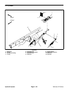
1. R port
2. E port
3. T port
4. P port
5. L port
Figure 40
FRONT OF
VEHICLE
2
1
3
4
5
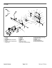
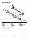
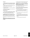
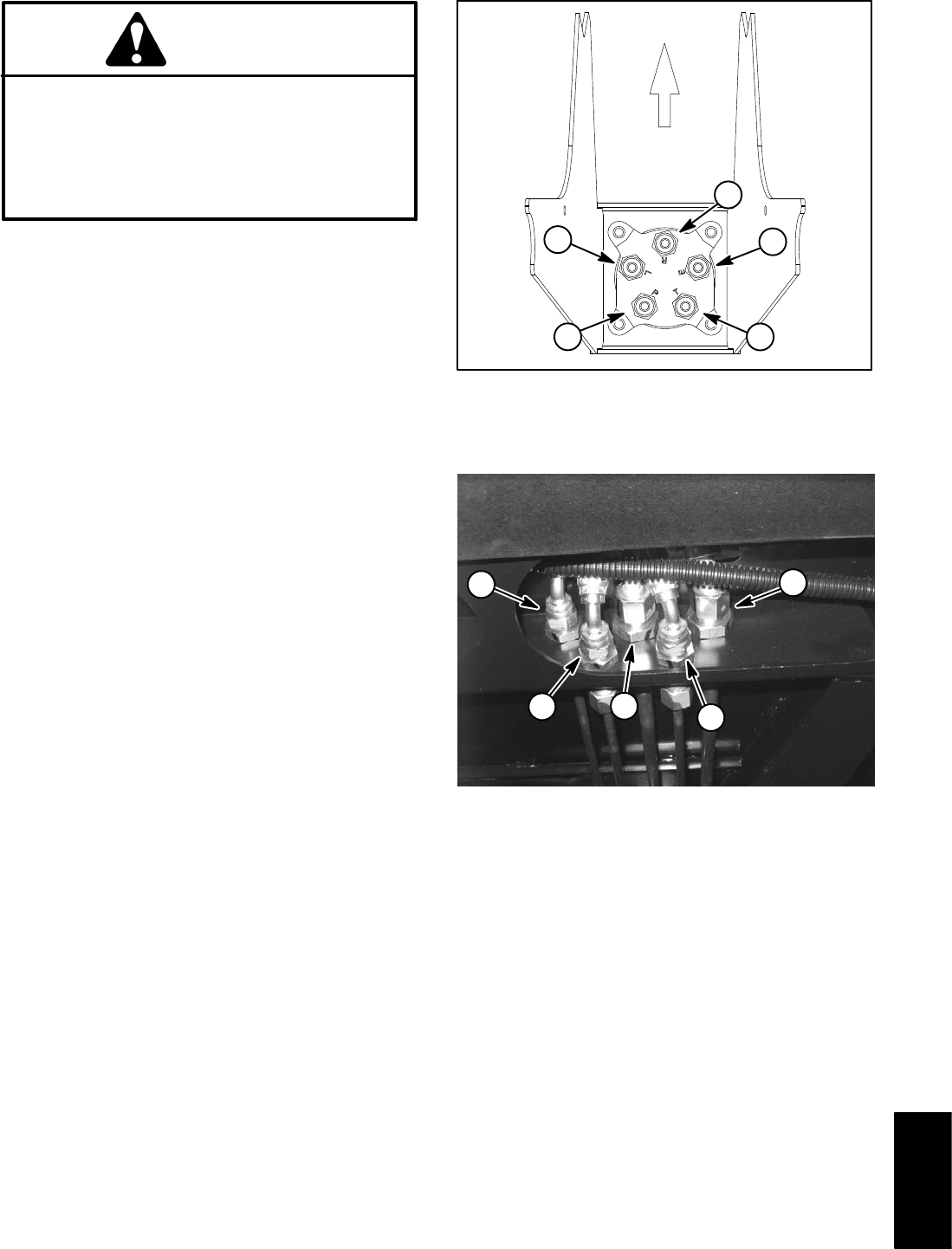
1. Hyd hose to L port
2. Hyd hose to R port
3. Hyd hose to P port
4. Hyd hose to T port
5. Hyd hose to E port
Figure 41
2
5
1
3
4
Hydraulic
System