


Workman HD Series Page 8 − 19 Electrical System
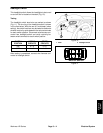
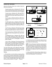
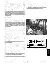
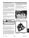
4. Connect multimeter (ohms setting) leads to relay ter-
minals 30 and 87 (Fig. 23). Ground terminal 86 and apply
+12 VDC to terminal 85. The relay should make and
break continuity between terminals 30 and 87 as +12
VDC is applied and removed from terminal 85.
5. Disconnect voltage from terminal 85 and multimeter
lead from terminal 87.
6. Connect multimeter (ohms setting) leads to relay ter-
minals 30 and 87A. Apply +12 VDC to terminal 85. The
relay should make and break continuity between termi-
nals 30 and 87A as +12 VDC is applied and removed
from terminal 85.
7. Disconnect voltage and multimeter leads from the
relay terminals.
8. Replace relay if testing determines that relay is faulty.
9. After testing is complete, secure relay to machine
and connect wire harness connector to relay.
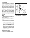
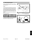
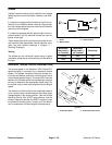
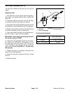
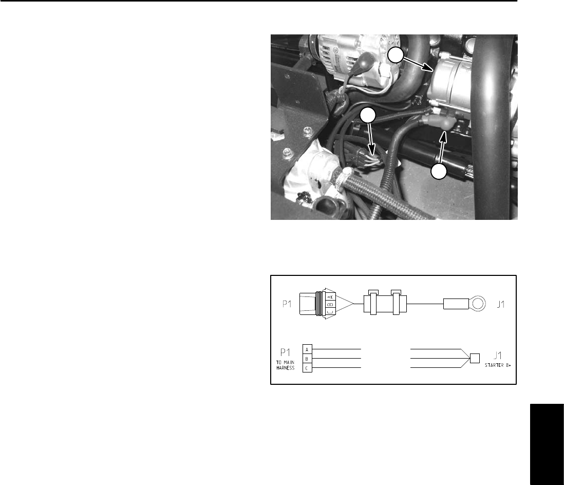
Fusible Link
A Workman HD series vehicle uses three (3) fusible links
for circuit protection. These fusible links are located in a
harness that connects the starter B+ terminal to the ve-
hicle wire harness (Fig. 24). If any of these links should
fail, current to the protected circuit will cease. Refer to
electrical schematics and wire harness drawings in
Chapter 11 − Electrical Drawings for additional fusible
link information.
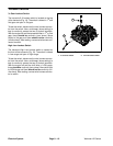
Testing
1. Park machine on a level surface, raise bed, stop en-
gine, apply parking brake and remove key from ignition
switch.
2. Install bed support on bed lift cylinder to prevent bed
from lowering.
3. Disconnect negative battery cable from battery ter-
minal and then disconnect positive cable from battery
(see Battery Service in the Service and Repairs section
of this chapter).
4. Locate and unplug fusible link connector P1 from ve-
hicle wire harness.
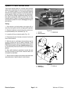
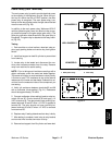
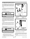
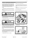
5. Use a multimeter to make sure that continuity (zero
ohms) exists between each terminal pin in connector P1
and connector J1 at the starter (Fig. 25). If any of the fus-
ible links are open (infinite ohms), replace the fusible link
harness.
6. After testing is complete, make sure that fusible link
harness connectors are securely attached to starter and
vehicle wire harness.
7. Connect positive battery cable to battery terminal
first and then connect negative cable to battery.
8. Remove bed support from lift cylinder and lower bed.
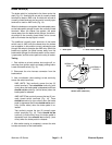
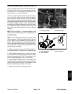
1. Starter motor
2. Fusible link harness
3. Starter B+ terminal
Figure 24
2
1
3
Figure 25
FUSIBLE LINK
FUSIBLE LINK
FUSIBLE LINK
Electrical
System