


Workman HDX Page 3 − 15 Kubota EFI Gasoline Engine
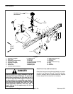
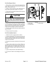
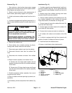
Removal (Fig. 12)
1. Park vehicle on a level surface, stop engine, engage
parking brake and remove key from the ignition switch.
Allow engine and radiator to cool.
2. Raise or remove the bed or other attachment(s). If
bed is raised, place safety support on lift cylinder.
3. Unlatch and remove radiator screen from front of ra-
diator.
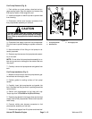
4. If vehicle is equipped with high flow hydraulics kit, ro-
tate oil cooler latches and place oil cooler away from ra-
diator.
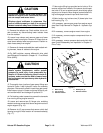
CAUTION
Do not open radiator cap or drain coolant if the
radiator or engine is hot. Pressurized, hot cool-
ant can escape and cause burns.
Ethylene−glycol antifreeze is poisonous. Dis-
pose of coolant properly or store it in a properly
labeled container away from children and pets.
5. Remove the radiator cap.
6. Drain radiator into a suitable container by discon-
necting lower radiator hose from the radiator.
7. Disconnect upper radiator hose from the radiator.
8. Disconnect reservoir hose from the radiator filler
neck.
9. Disconnect wire harness connector from radiator
fan.
10.Detach radiator assembly from radiator mount:
A. Remove two (2) flange head screws and flat
washers that secure the top of the radiator assembly
to the mount.
B. Remove two (2) flange head screws and flange
nuts that secure the bottom of the radiator assembly
to the mount.
11. Carefully separate radiator assembly from mount
and remove from vehicle.
12.Plug all radiator and hose openings to prevent con-
tamination.
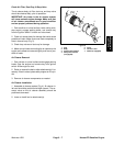
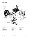
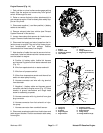
13.If necessary, remove components from radiator (Fig.
13).
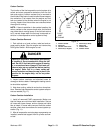
Installation (Fig. 12)
1. If radiator assembly was disassembled, install com-
ponents to radiator using (Fig. 13) as a guide. Make sure
that clearance exists between shroud and fan at all
points.
2. Remove plugs from radiator openings and hoses
placed during the removal procedure.
3. Position radiator assembly to the radiator mount. Se-
cure radiator assembly to the vehicle with removed
flange head screws, flat washers and flange nuts.
4. Connect reservoir hose to the radiator filler neck. Se-
cure hose with hose clamp.
5. Connect upper and lower hoses to the radiator. Se-
cure hoses with hose clamps.
6. Connect wire harness connector to radiator fan.
7. Fill radiator with coolant to the bottom of the filler
neck.
8. If vehicle is equipped with high flow hydraulics kit,
position oil cooler to radiator and secure in place.
9. Install and latch the radiator screen.
10.Lower or install bed or other attachment(s).
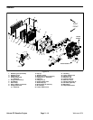
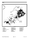
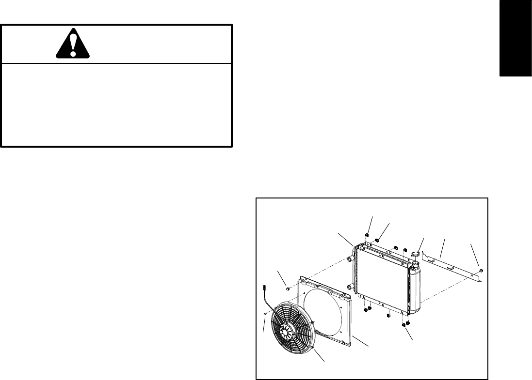
Figure 13
1. Radiator
2. Electric fan
3. Shroud
4. Latch (2 − oil cooler)
5. Flange screw (7)
6. Nut (7)
7. Screw (4)
8. Lower mount plate
9. Radiator cap
2
3
1
5
4
6
7
8
9
5
6
Kubuta EFI
Gasoline Engine