


Workman HD Series Page 7 − 21 Chassis
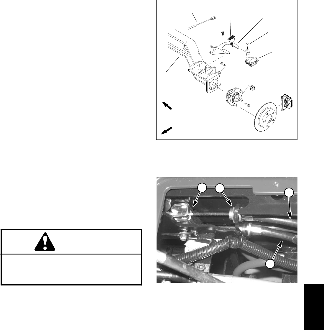
7. Remove retaining ring that secures brake cable to le-
ver support assembly.
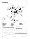
8. Disconnect brake cable from cable equalizer bracket
(Fig. 14).
9. Note routing of parking brake cable and location of
cable ties to secure brake cable to vehicle frame. Re-
move brake cable from vehicle.
Installation (Fig. 12)
1. Route new brake cable in same location as before
and secure with cable ties. Start from rear of vehicle and
work towards front.
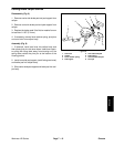
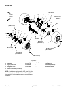
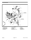
2. Connect brake cable to parking brake caliper on rear
axle (Fig. 13).
A. Connect parking brake cable to parking brake
caliper lever with clevis pin.
B. Secure clevis pin by inserting return spring end
into clevis pin.
C. Tighten cable jam nuts to secure parking brake
cable to brake bracket. Position jam nuts so that all
threads on cable are showing towards the rear of the
vehicle.
3. Install brake cable end to brake equalizer on parking
brake lever. Secure brake cable to lever support assem-
bly with retaining ring (Fig. 14).
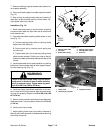
WARNING
Failure to maintain proper wheel lug nut torque
could result in failure or loss of wheel and may
result in personal injury. Torque wheel lug nuts
from 80 to 90 ft−lb (109 to 122 N−m).
4. Install rear wheel (see Wheel Installation in this sec-
tion). Lower vehicle to ground and make sure that wheel
lug nuts are properly torqued from 80 to 90 ft−lb (109
to 122 N−m).
5. Secure center console control plate to seat base with
removed screws. Torque screws a maximum of 12 in−lb
(1.3 N−m).
6. Install control lever knobs.
7. Adjust parking brake lever (see vehicle Operator’s
Manual) and check operation of brakes before returning
the vehicle to service.
5
3
2
1
4
6
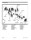
Figure 13
1. Parking brake cable
2. Clevis pin
3. Brake return spring
4. Parking brake bracket
5. Parking brake caliper
6. Rear axle
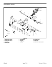
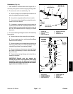
FRONT
RIGHT
1. Brake cable
2. Retaining ring location
3. Equalizer bracket
Figure 14
1
2
1
3
Chassis