


Workman HD
Page 5 − 13
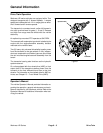
Kohler Air Cooled Gasoline Engine
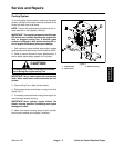
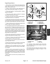
Engine Removal (Fig. 6)
1. Park vehicle on a level surface and engage parking
brake. Stop the engine and remove key from ignition
switch. Allow engine to cool.
2. Raise or remove the bed or other attachment(s). If
bed is raised, place safety support on lift cylinder.
3. Disconnect negative (−) and then positive (+) battery
cables at the battery.
4. Disconnect positive cable and fusible link harness
from starter solenoid stud on engine.
5. Remove the muffler and exhaust manifold (see Ex-
haust System Removal in this section).
6. Disconnect fuel hose from fuel pump on engine. Plug
end of fuel hose to prevent contamination and fuel spill-
age. Position disconnected fuel hose away from engine.
7. Label and disconnect wire harness connectors that
attach to engine and engine accessories.
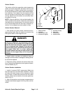
8. Loosen fasteners that secure hydraulic pump to en-
gine mount (Fig. 7). Rotate pump toward engine to allow
drive belt to be removed from pump and engine pulleys.
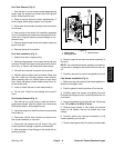
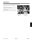
9. Disconnect accelerator cable shoulder bolt from
throttle lever on engine. Loosen jam nuts on cable and
remove cable from throttle bracket. Position accelerator
cable away from engine (Fig. 8).
10.Disconnect choke cable from choke lever on engine.
Remove choke cable from bracket (Fig. 8).
11. Remove all clamps and cable ties that attach wire
harness, hoses and cables to the engine.
12.Put blocking under transaxle to prevent it from mov-
ing during engine removal.
13.Loosen and remove four (4) flange nuts and flange
head screws that secure engine to engine mount.
14.Remove six (6) cap screws and two (2) harness
brackets that secure clutch bell housing to clutch adapt-
er on engine.
15.Use lift or hoist to remove engine from chassis. One
person should operate hoist and a second person
should help guide engine out of chassis. Move engine
forward before lifting to disengage transaxle input shaft
from clutch.
16.Note location and retrieve two (2) dowel pins from
bell housing.
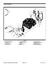
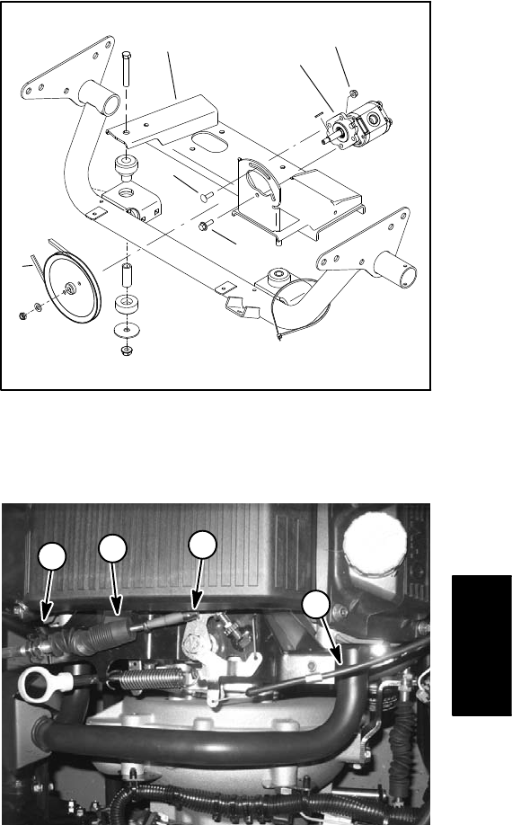
Figure 7
1. Hydraulic pump
2. Flange nut (2)
3. Engine mount
4. Pump drive belt
5. Carriage screw
6. Flange head screw
2
3
5
6
4
1
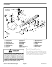
Figure 8
1. Accelerator cable
2. Ball joint
3. Jam nuts
4. Choke cable
1
3
2
4
17.If necessary, remove hydraulic pump drive pulley
from stub shaft on flywheel side of engine. Locate and
retrieve woodruff key.
18.If pressure plate and clutch disc removal is neces-
sary, see Clutch Service and Repair in Chapter 6 − Drive
Train in this manual.
Kohler Air Cooled
Gasoline Engine