


Workman HD Series Page 8 − 21 Electrical System
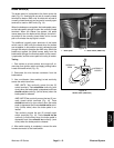
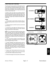
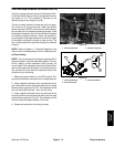
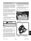
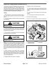
Fuel Run/Stop Solenoid (Workman HDX−D)
The fuel run/stop solenoid used on the Workman HDX−
D (Kubota Diesel engine) must be energized for the die-
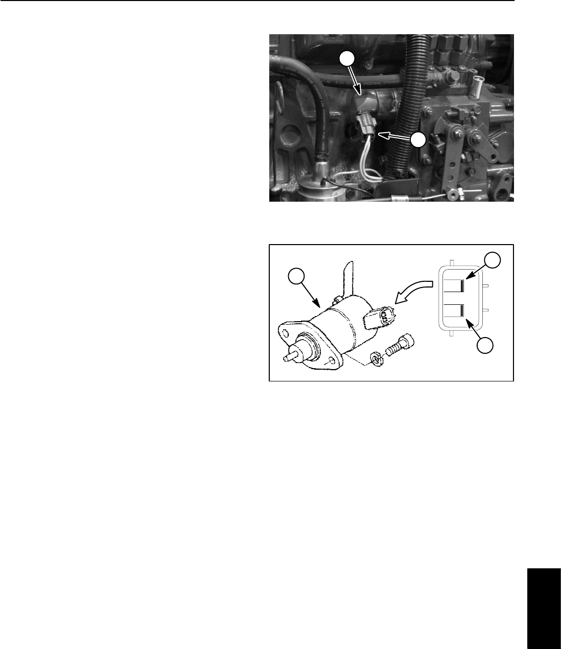
sel engine to run. The solenoid is mounted to the
injection pump on the engine (Fig. 28).
The fuel run/stop solenoid includes two coils for opera-
tion, the pull coil and the hold coil. When the ignition
switch is turned to START, the solenoid is initially energi-
zed and the pull coil retracts the solenoid plunger. Once
the plunger is retracted, the hold coil will keep it retracted
for continued engine operation. When the solenoid is
de−energized, the plunger extends to shut off fuel supply
to the engine causing the engine to stop running. The
fuel run/stop solenoid is grounded through the solenoid
housing.
NOTE: Refer to Chapter 11 − Electrical Diagrams in this
manual when troubleshooting the fuel run/stop solenoid.
In Place Testing
NOTE: Prior to taking small resistance readings with a
digital multimeter, short the test leads together. The me-
ter will display a small resistance value (usually 0.5
ohms or less). This resistance is due to the internal resis-
tance of the meter and test leads. For accurate test res-
ults, subtract this value from the measured value of the
component you are testing.
1. Make sure ignition switch is in the OFF position. Dis-
connect wire harness connector from run/stop solenoid.
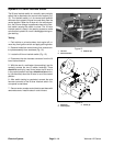
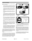
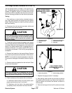
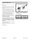
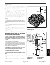
2. Using a digital multimeter, touch one test lead to the
pull coil terminal and the other test lead to the run/stop
solenoid frame (ground) (Fig. 29). The resistance of the
pull coil should be less than 1 ohm (but not zero).
3. Using a digital multimeter, touch one test lead to the
hold coil terminal and the other test lead to the fuel stop
solenoid frame (ground) (Fig. 29). The resistance of the
hold coil should be approximately 15.5 ohms.
4. Reconnect solenoid to the wiring harness.
1. Fuel stop solenoid 2. Harness connector
Figure 28
2
1
1. Fuel stop solenoid
2. Pull coil terminal
3. Hold coil terminal
Figure 29
2
3
1
Electrical
System