


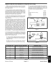
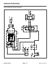
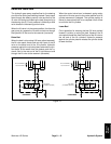
Workman HD Series Page 9 − 13 Hydraulic System
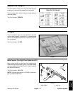
Raise and Lower Bed
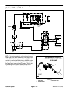
The hydraulic gear pump supplies flow for the steering
circuit and for raising and lowering the bed. Pump output
flows through the steering control valve and then to the
lift valve for raising and lowering the bed (flow priority to
the steering circuit). Circuit pressure is limited by a relief
valve located in the steering control valve.
When the lift valve is in the center position, flow from the
gear pump by−passes the lift valve and returns through
the hydraulic oil filter and to the reservoir (transaxle).
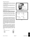
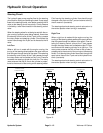
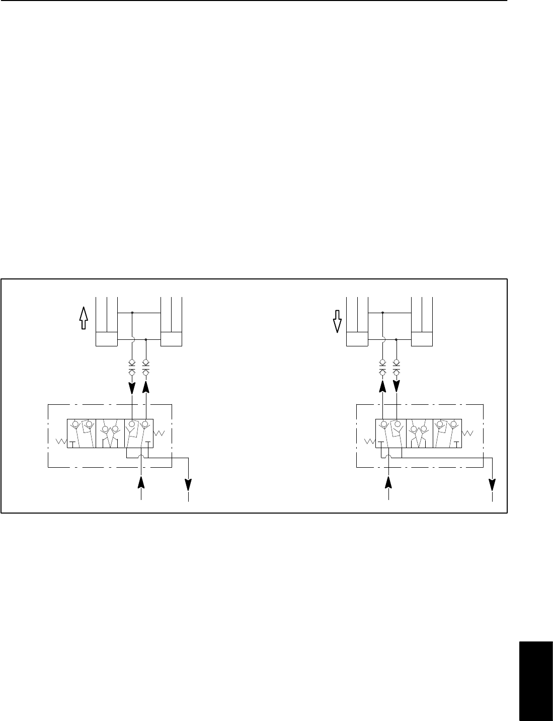
Raise Bed
When the bed is to be raised (lift lever pulled rearward),
the lift valve spool directs flow out the A port of the lift
valve to the barrel end of the lift cylinders. Hydraulic
pressure against the cylinder pistons extends the cylin-
der shafts. At the same time, the pistons push the hy-
draulic fluid in the rod end of the lift cylinders out and
through the lift valve to the reservoir (transaxle).
When the control valve lever is released, spring action
returns the lift valve spool to the center position and lift
cylinder movement is stopped. The cylinder position is
locked in place since there is no complete circuit of flow
to and from the lift cylinders.
Lower Bed
Circuit operation for lowering the bed (lift lever pushed
forward) is similar to raising the bed. However, the lift
valve spool directs flow from the B port of the lift valve to
the rod end of the lift cylinders. Hydraulic pressure
against the cylinder pistons retracts the cylinder shafts
to lower the bed.
Figure 14
LIFT CYLINDERS (2)
PISTON MOVEMENT
LOWER BED
LIFT CYLINDERS (2)
PISTON MOVEMENT
RAISE BED
LIFT VALVE
(IN LOWER POSITION)
LIFT VALVE
(IN RAISE POSITION)
Hydraulic
System