


Workman HD SeriesPage 7 − 26Chassis
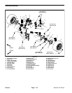
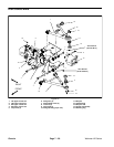
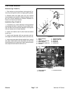
Assembly (Fig. 16)
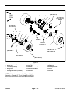
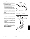
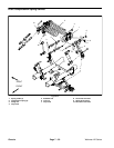
1. If steering linkage and center link is disassembled
(Fig. 17 and 18).
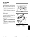
A. If flange bushings (Fig. 18) were removed from
pivot mount, make sure that new bushings are
pressed fully into the pivot mount.
B. Fill pivot mount cavities with grease.
C. Torque new spindle nut to 85 ft−lb (115 N−m).
Deform spindle nut into slot in idler arm or pitman arm
after torquing nut.
D. If bearings were removed from center link, press
new bearings fully to the shoulder of the bearing bore
in the center link. Secure bearings with retaining ring.
E. Secure center link to steering linkage with cap
screws, washers and flange nuts. Torque flange nuts
from 40 to 50 ft−lb (55 to 67 N−m).
2. If steering linkage and center link assembly was re-
moved from vehicle:
A. Position assembly to frame and secure with re-
moved fasteners. Torque lock nuts from 40 to 50 ft−
lb (55 to 67 N−m).
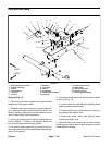
B. Secure steering cylinder ball joint to steering link-
age with slotted hex nut. Torque slotted hex nut from
80 to 90 ft−lb (109 to 122 N−m). If necessary, tighten
nut further until slot in nut aligns with hole in ball joint
stud. Install cotter pin.
C. Install tie rods to center link (see below).
D. Install seat base to vehicle (see Seat Base Instal-
lation in this section).
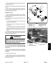
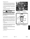
3. To install tie rod to vehicle:
A. If tie rod was separated, make sure that jam nut is
on inner tie rod threads. Thread outer tie rod end
onto inner tie rod the same number of revolutions as
the old one took to remove.
B. Apply Loctite #271 (or equivalent) to threads of
inner tie rod end. Thread tie rod into center link and
torque from 70 to 80 ft−lb (94 to 109 N−m).
C. Clean tapers of knuckle and outer tie rod end ball
joint stud.
D. Insert outer tie rod end ball joint stud into knuckle
and secure with slotted hex nut. Torque slotted hex
nut from 35 to 40 ft−lb (48 to 55 N−m). If necessary,
tighten nut further until slot in nut aligns with hole in
tie rod ball joint stud. Install cotter pin.
4. Lubricate all grease fittings in steering assembly.
Make sure steering linkage assembly pivot mount is
completely filled with grease.
5. Check front wheel alignment and adjust if necessary
(see Front Wheel Alignment in this section).