


Workman HD Series Page 6 − 21 Drive Train
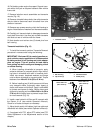
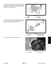
Clutch Disassembly and Inspection (Fig. 19)
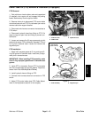
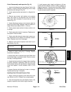
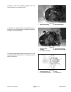
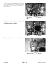
1. Insert clutch alignment tool (see Special Tools in this
chapter) in engine flywheel pilot bearing hole to keep
clutch disk from falling off (Fig. 20).
2. Loosen pressure plate cap screws in a diagonal se-
quence.
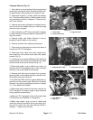
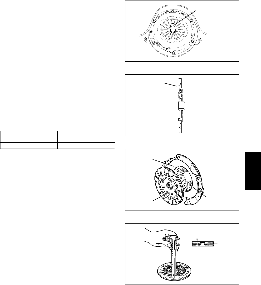
3. Remove cap screws, lock washers and pressure
plate, then slide out the alignment tool and remove
clutch disk. Note orientation of clutch disk as it is re-
moved (Fig. 21).
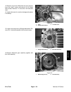
4. Inspect diaphragm spring end of pressure plate for
wear and uneven height. Replace if wear is evident or if
height difference exceeds 0.020 in. (0.5 mm).
5. Check pressure plate surface for wear, cracks or col-
or change.
6. Check strap plate rivets for looseness. Replace pres-
sure plate if rivets are loose.
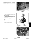
7. Check clutch disk facing for loose rivets, uneven con-
tact, deterioration due to seizure and lubricant contami-
nation. Replace clutch disk if damaged.
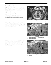
8. Measure rivet sink and replace clutch disk if out of
specification (Fig. 23).
Clutch disk thickness
standard value
0.307 to 0.339 in. (7.8 to 8.6
mm)
Clutch disk rivet sink 0.012 in. (0.3 mm) minimum
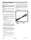
9. Check for torsion spring play or damage. Replace
clutch disk if necessary.
10.Install clutch disk on transaxle main shaft. Make sure
clutch slides freely on splines of shaft. Check for exces-
sive play in rotating direction.
11. Inspect flywheel surface for stepped wear, streaking
or seizure. Replace if necessary. Clean any oil or rust
from flywheel surface with light abrasive. Check flywheel
runout and replace if runout exceeds 0.005 in. (0.13
mm).
12.Inspect flywheel pilot bearing for wear or damage.
Replace pilot bearing if necessary.
Installing Clutch Disk and Pressure Plate
1. Apply a coating of grease to clutch disk spline, then
use a brush to rub it in. Wipe off any excess grease.
2. Use clutch alignment tool (see Special Tools in this
chapter) to position clutch disk to engine flywheel.
3. Install pressure plate. Install and tighten six (6) cap
screws and lock washers a little at a time, working in a
diagonal sequence. Torque screws from 5 to 7 ft−lb (7
to 9 N−m). Remove alignment tool from flywheel bear-
ing after pressure plate is installed.
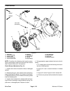
Clutch Alignment Tool
Figure 20
Pressure
Engine
Plate Side
Flywheel
Side
Clutch Disc
Figure 21
Torsion spring
Pressure plate
Diaphragm spring
Figure 22
Rivet sink
Figure 23
Drive Train