


Workman HD SeriesPage 8 − 18Electrical System
Relay (Five Terminals)
Workman HD series vehicles use a number of relays that
have five (5) terminals:
The start enable relay on Workman HD, HDX and
HDX−D vehicles ensures that the clutch pedal is de-
pressed before the engine starter can be engaged.
The start relay on Workman HD, HDX and HDX−D
vehicles ensures that the hydraulic lift lever is in
neutral before the engine starter solenoid can be en-
ergized.
The fan relay on Workman HDX and HDX−D ve-
hicles powers the engine cooling fan the relay is en-
ergized.
The ECU power relay on Workman HDX vehicles
supplies power to the engine Electronic Control Unit
(ECU), the fuel pump relay, the engine Oxygen (O2)
sensor, and the Electronic Throttle Valve (ETV) re-
lay.
The ETV relay on Workman HDX vehicles provides
power to the engine Electronic Throttle Valve (ETV)
through the engine Electronic Control Unit (ECU).
The fuel pump relay on Workman HDX vehicles al-
lows current to the fuel pump when the relay is ener-
gized.
The differential relay on Workman HDX 4WD and
HDX−D 4WD vehicles are used to make sure that
the front wheel drive differential solenoid is not ener-
gized when the clutch is disengaged or when the
brake is applied.
The kill relay on Workman HD vehicles allows the
engine to run as long as the relay is energized. If the
ignition switch is in the OFF position or the transmis-
sion lockout switches are all open, the relay will not
be energized and the engine will stop running.
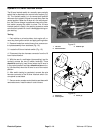
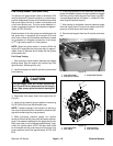
The start enable relay and the differential relay (4WD
vehicles) are located behind the dash panel. The other
relays are attached to the relay bracket under the right
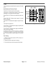
side of the bed near the rear axle (Fig. 22).
Testing
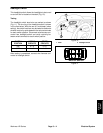
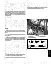
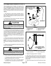
1. Park machine on a level surface and apply parking
brake. If relay is located on relay bracket, raise bed and
install bed support on bed lift cylinder to prevent bed
from lowering. Stop engine and remove key from ignition
switch. If relay is located behind dash panel, remove
hood (see Hood Removal in Chapter 7 − Chassis).
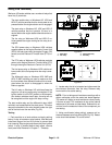
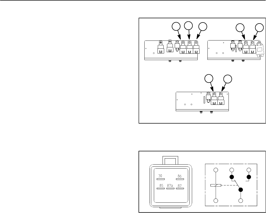
1. Start relay
2. Fan relay
3. Fuel pump relay
4. Kill relay
Figure 22
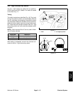
HDX MODELS
HDX−D MODELS
HD MODELS
1
1
2
1
2
3
4
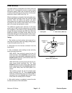
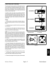
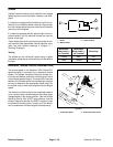
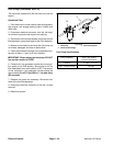
Figure 23
86
85
87A 87
30
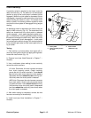
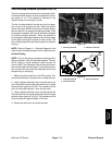
2. Locate relay that is to be tested and disconnect the
wire harness connector from the relay. Remove relay
from machine for easier testing.
NOTE: Prior to taking small resistance readings with a
digital multimeter, short the meter test leads together.
The meter will display a small resistance value (usually
0.5 ohms or less). This resistance is due to the internal
resistance of the meter and test leads. Subtract this val-
ue from from the measured value of the component you
are testing.
3. Using a multimeter (ohms setting), measure coil re-
sistance between terminals 85 and 86 (Fig. 23). Resist-
ance should be between 70 and 90 ohms.